High-efficiency LED (light emitting diode) driving circuit

A LED driving and high-efficiency technology, applied in the electronic field, can solve the problems of complex power switch tube driving circuit and inaccurate sampling accuracy, and achieve the effects of reducing cost and power consumption, improving modulation accuracy, and reducing volume

Active Publication Date: 2013-06-12
SILERGY SEMICON TECH (HANGZHOU) CO LTD
View PDF9 Cites 2 Cited by
  • Summary
  • Abstract
  • Description
  • Claims
  • Application Information

AI Technical Summary

Problems solved by technology

[0007] In view of this, the object of the present invention is to provide a high-efficiency LED drive circuit, which can be configured as a step-down drive circuit and a boost-buck drive circuit through the setting of peripheral circuits to solve the problem of power switch tube drive. The problem of complex circuit and inaccurate sampling accuracy

Method used


Image

  • High-efficiency LED (light emitting diode) driving circuit
  • High-efficiency LED (light emitting diode) driving circuit
  • High-efficiency LED (light emitting diode) driving circuit

Examples


Embodiment Construction

[0049] The LED drive circuit in the embodiment of the present invention is configured as different buck drive circuits and boost-buck drive circuits matching the application by setting different peripheral circuits.

[0050] Various embodiments of the step-down LED driving circuit of the present invention will be described in detail below.

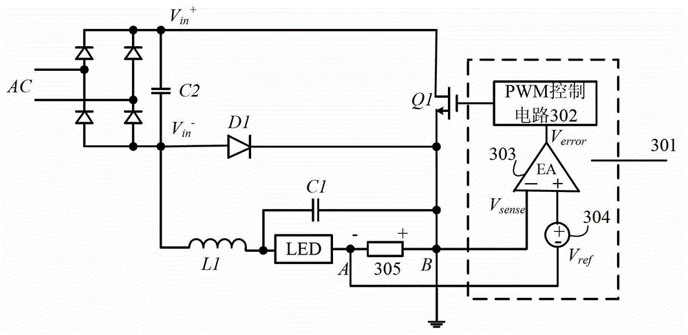
[0051] refer to Figure 3A , which is a functional block diagram of an embodiment of the step-down LED driving circuit of the present invention. In this embodiment, the AC input power supply AC is converted into a DC power supply after passing through the rectifier bridge and the filter capacitor C2, which has a first input level V in + and the second input level V in - .

[0052] The power switch tube Q1, the output diode D1, the output inductor L1, and the output capacitor C1 form a power stage circuit with a step-down topology. Of course, the output capacitor C1 is not necessary, and it can be omitted in some applications. Here, ...


PUM


Abstract

The invention relates to a high-efficiency LED (light emitting diode) driving circuit, which is used for driving an LED device. The LED driving circuit comprises a control circuit, an LED current detection circuit and a power switch tube, wherein the LED current detection circuit is used for generating a feedback signal for representing a driving signal of the driving current of the LED device, the control circuit is connected with the LED current detection circuit, and is used for receiving the feedback signal and generating a PWM (pulse width modulation) driving signal, the power switch tube is used for receiving an input voltage source and the PWM driving signal, and is periodically conducted and cut off to drive the LED device, and the driving current of the LED device is maintained constant.

Description

[0001] This application is a divisional application with the application number 201110005323.6, the application date is January 10, 2011, and the title of the invention is "a high-efficiency LED driving circuit and driving method". technical field [0002] The present invention relates to the field of electronic technology, and more specifically, relates to a driving circuit applied to an LED device. Background technique [0003] With the continuous innovation and rapid development of the lighting industry, coupled with the increasing importance of energy saving and environmental protection, LED lighting, as a revolutionary energy-saving lighting technology, is developing rapidly. However, since the brightness of an LED lamp is related to the light output intensity parameter, it is directly proportional to its current and forward voltage drop, and changes with temperature. Therefore, the driving of LED requires a constant current power supply to ensure the safety of LED use ...

Claims


Application Information

Patent Timeline
Patent Type & Authority Applications(China)
IPC IPC(8): H05B37/02
CPCH05B45/14H05B45/375H05B45/3725
Inventor 陈伟陈圣伦
Owner SILERGY SEMICON TECH (HANGZHOU) CO LTD
Why Eureka
Try Eureka