Torque transmission device

A technology of torque transmission device and clutch, applied in the direction of transmission device, differential transmission device, transmission device control, etc., to achieve the effect of low cost, reliable cost and simple stop

Inactive Publication Date: 2013-06-12
MAGNA STEYR FAHRZEUGTECHN
View PDF7 Cites 5 Cited by
  • Summary
  • Abstract
  • Description
  • Claims
  • Application Information

AI Technical Summary

Problems solved by technology

This requires a very robust design of the locking mechanism, which entails corresponding manufacturing costs

Method used


Image

  • Torque transmission device

Examples


Embodiment Construction

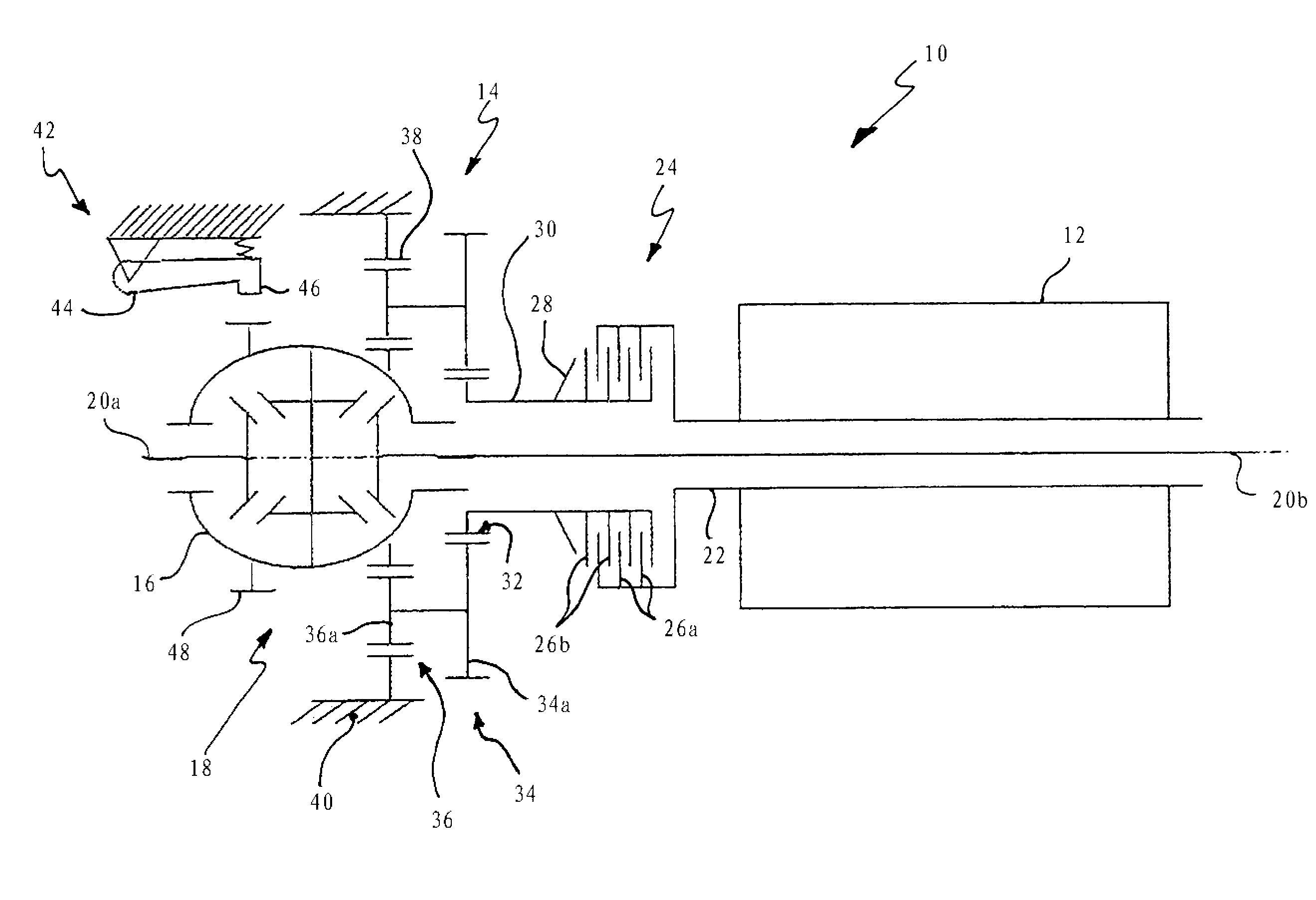
[0017] The driving of the differential mechanism 18 can realize the transmission of the driving torque generated by the electric motor 12 to the half shafts 20a, 20b connected to the wheels of the motor vehicle not shown. The electric motor 12 has a rotor connected to a hollow shaft 22 in a rotationally fixed manner. The hollow shaft 22 is connected to a slip clutch 24 functionally arranged between the electric motor 12 and the speed reducer 14. The slip clutch 24 is designed as a diaphragm clutch and includes alternately arranged outer friction plates 26a and inner friction plates 26b forming a diaphragm stack. The disc spring 28 presses the diaphragms 26a, 26b against each other with a predetermined force so as to provide a clearly defined clutch between the hollow shaft 22 coaxially surrounding the half shaft 20b and the input shaft 30 of the reducer 14.

[0018] The reducer 14 is designed as a two-stage planetary gear transmission. The input shaft 30 is connected to the sun...


PUM


Abstract

The present invention relates to a torque transmission device for a motor vehicle, with a blocking mechanism for locking at least one motor vehicle wheel connected to an output shaft of the torque transmission device. The torque transmission device comprises a differential gearing connected to the output shaft and a drive unit, and said differential gearing and the drive unit are connected to each other effectively in terms of drive via a clutch unit. The blocking mechanism can be brought into engagement with a rotatable component of the torque transmission device, which component is functionally arranged between the wheel and the clutch unit.

Description

Technical field [0001] The invention relates to a torque transmission device for a motor vehicle, which has a locking mechanism for stopping at least one motor vehicle wheel connected to an output shaft of the torque transmission device. Background technique [0002] Such a torque transmission device with a locking mechanism is used in many kinds of motor vehicles, especially in electric vehicles or hybrid vehicles. The locking mechanism can be used as a parking lock, for example, to prevent the motor vehicle from sliding down in the parked state. It is particularly important here that the stopping is reliably performed so that the safety of the motor vehicle can always be ensured even if the load on the locking mechanism is high (for example, when the motor vehicle is parked on a slope). This locking mechanism must also be designed so that it can be inserted even when the motor vehicle is still rolling at a slow speed. This requires a very strong structural solution for the lo...

Claims


Application Information

Patent Timeline
Patent Type & Authority Applications(China)
IPC IPC(8): F16H63/34F16H63/48B60T1/00
CPCB60K2001/001B60T1/005F16H63/3425F16H48/22
Inventor F.坦格尔S.皮克勒
Owner MAGNA STEYR FAHRZEUGTECHN
Why Eureka
Try Eureka