Method capable of quantificationally taking out objects contained in container
A technology for containers and contents, which is applied to quantitatively taking out the contents in the container, can be limited in the field, can solve the problem of inconvenient access to the contents in the container, etc., and achieves the improvement of the scientific living standard, good adaptability and simple method. Effect
- Summary
- Abstract
- Description
- Claims
- Application Information
AI Technical Summary
Problems solved by technology
Method used
Image
Examples
Embodiment 1
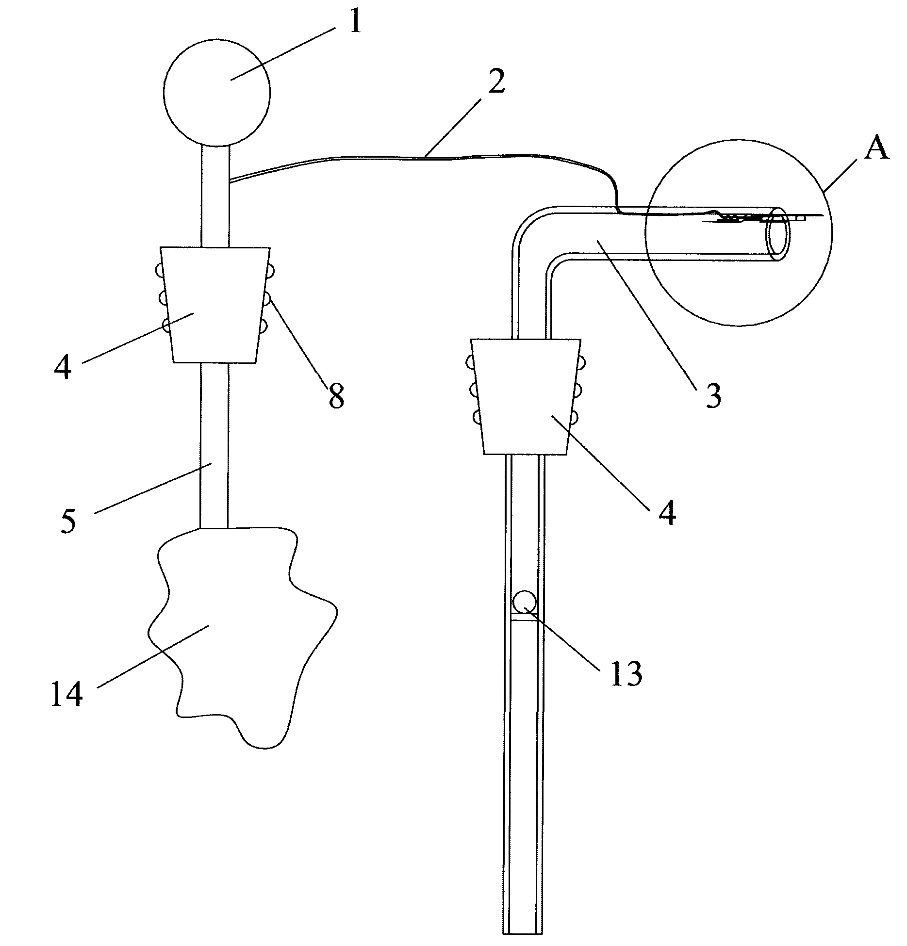
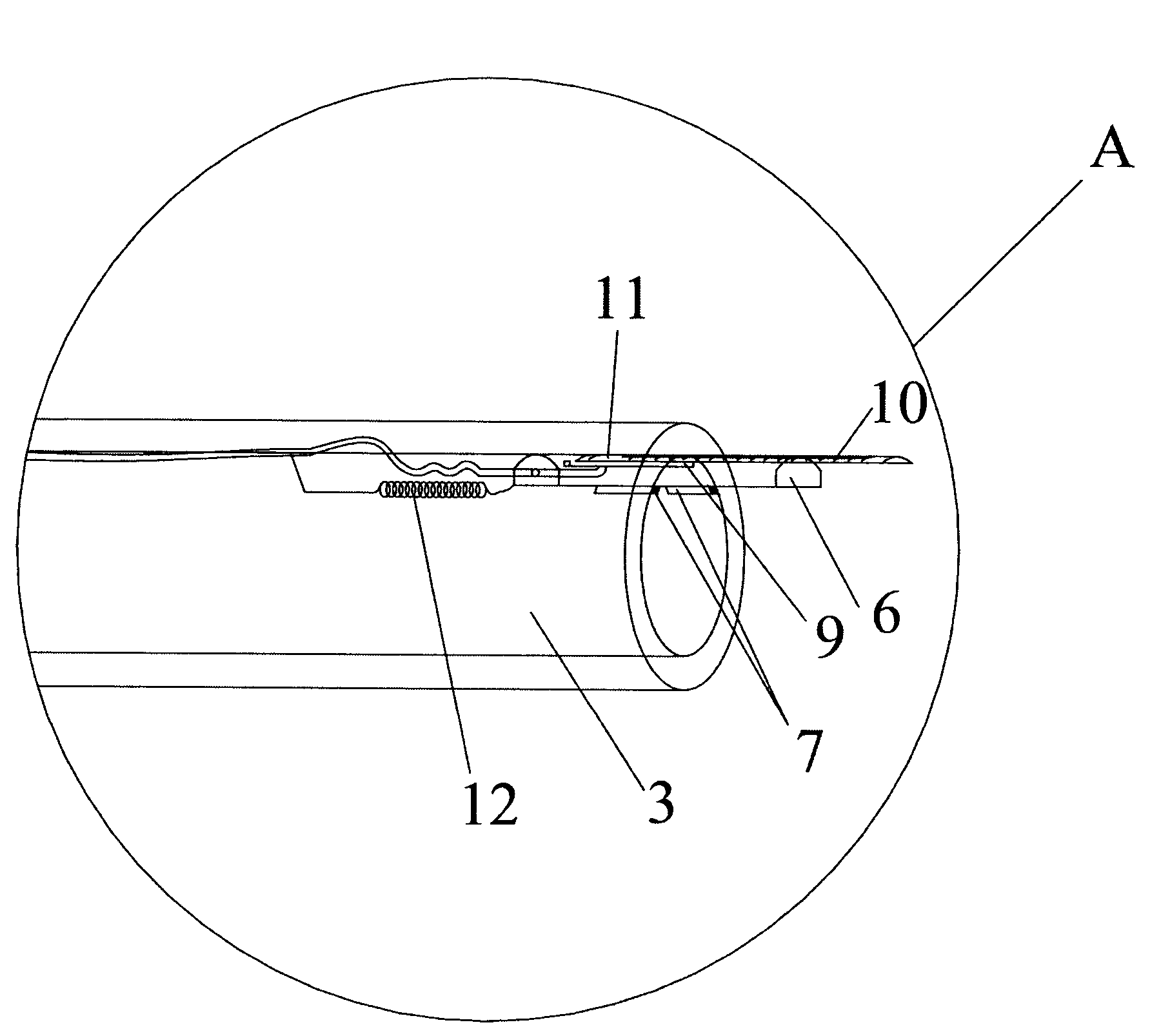
[0054] Such as figure 1 As shown, it is a device that can conveniently take out the contents of the container according to Embodiment 1 of the present invention, figure 2 for figure 1 Enlarged view of part A. The device, which can be used to dispense the paste, comprises a pressurized bladder 1, a control air channel 2, an outflow channel 3 and a large sealing member 4 for sealing the container. The control air channel 2 is located outside the container, and communicates with the gas in the container through a pressurized gas channel 5 . A plurality of annular elastic ribs 8 are provided on the outer peripheral wall of the large sealing member 4 . The large sealing part 4 seals all openings between the container and the outside world, and allows the pressurized gas channel 5 and the outflow channel 3 to pass therethrough. The pressurized airbag 1 takes in air from the outer end and outputs air from the inner end, which can continuously pressurize the gas space in the cont...
Embodiment 2
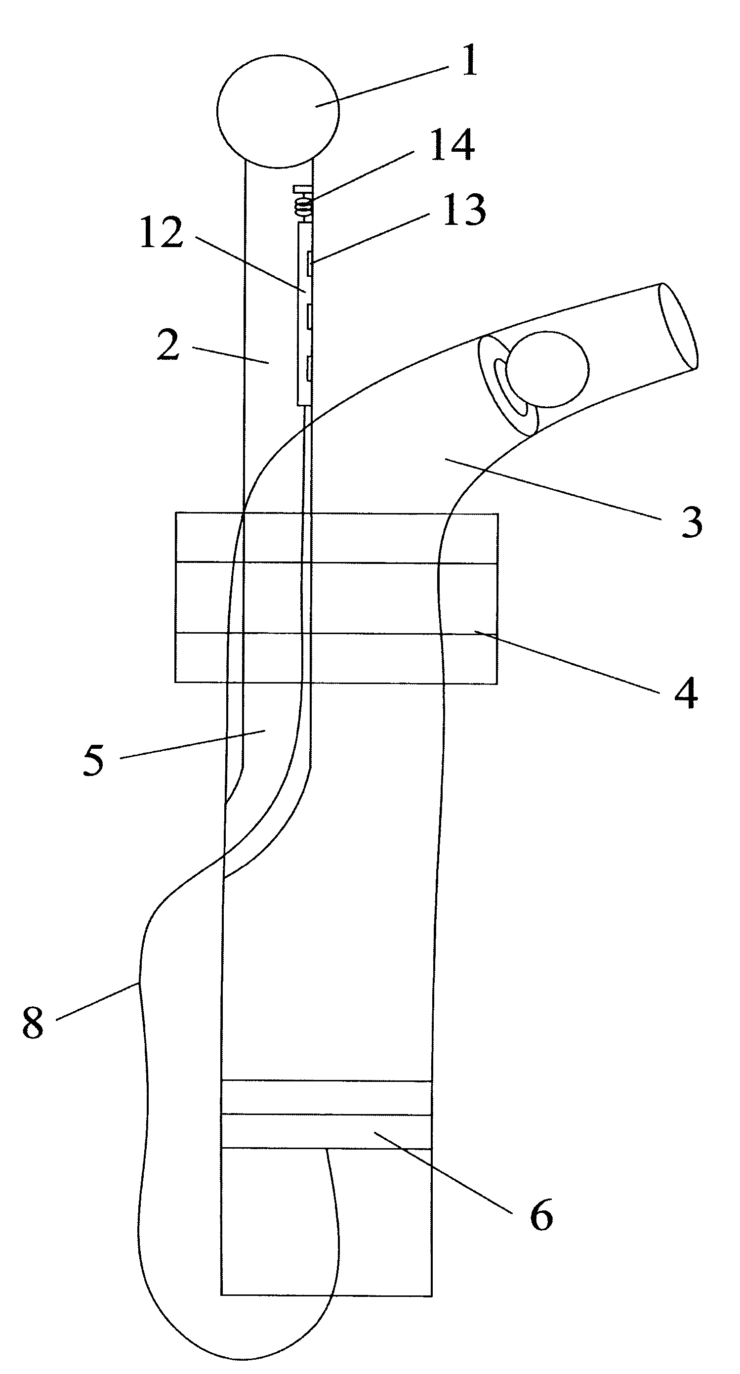
[0061] Such as image 3 As shown, it is a kind of utensil that can limit the amount of taking the contents of the container according to the embodiment 2, Figure 4 , Figure 5 It is the state diagram of piston 6. The device can be used to take liquid, including a pressurized air bag 1 , a control air channel 2 and an outflow channel 3 . The pressurized air bag 1 communicates with the air channel 5 through the control air channel 2, and is used for communicating with the gas space in the container. The airway 5 is part of the control airway 2 . The most distal end of control airway 2 is closed. The air channel 5 is located in the outflow channel 3 , but the gas in it is not communicated with the outflow channel 3 . The large sealing element 4 can seal the gap between the outflow channel 3 and the opening of the container.
[0062] The moving part in the outflow channel 3 is the piston 6, which is composed of the rim 9, the spokes 10 and the annularly arranged thin slices...
Embodiment 3
[0066] Such as Image 6 As shown, it is a kind of utensil that can conveniently take the contents in the container according to embodiment 3, Figure 7 for Image 6 Top view of the middle pulley. The appliance can be used to take liquid or paste, and includes a mechanical pressure device 1 , an outflow channel 3 and a control air channel 2 . The mechanical pressurizing device 1 is connected with a three-way valve 7, and when the three-way valve 7 is connected with the airway 6, it pressurizes the large sealing part 4, and when it is connected with the airway 5, it pressurizes the inside of the container and the control airway 2. The lengths of the air channel 5 and the outflow channel 3 at the bottom of the large sealing part 4 can be adjusted respectively.
[0067] On the 3 walls of the outflow passage, the runner 8 of the waterwheel structure is installed. The runner 8 is fixed on the wall of the outflow channel 3, and part of the fans of the runner are in contact with t...
PUM
 Abstract
Description
Claims
Application Information
 - R&D
- Intellectual Property
- Life Sciences
- Materials
- Tech Scout
- Unparalleled Data Quality
- Higher Quality Content
- 60% Fewer Hallucinations
Browse by: Latest US Patents, China's latest patents, Technical Efficacy Thesaurus, Application Domain, Technology Topic, Popular Technical Reports.
© 2025 PatSnap. All rights reserved.Legal|Privacy policy|Modern Slavery Act Transparency Statement|Sitemap|About US| Contact US: help@patsnap.com


