An electric calcining furnace for a graphite carbon material

An electric calcination furnace and graphite carbon technology, applied in the direction of non-metallic elements, inorganic chemistry, carbon compounds, etc., can solve the problems of short distance, easy oxidation of upper conductive electrodes and carbon raw materials, etc., to reduce oxidation loss and air tightness Enhance and reduce the effect of air flow

Active Publication Date: 2015-04-08
GUIYANG AL-MG DESIGN & RES INST
View PDF5 Cites 0 Cited by
  • Summary
  • Abstract
  • Description
  • Claims
  • Application Information

AI Technical Summary

Problems solved by technology

At the same time, the distance between the cavity under the furnace cover and the furnace top hopper is short, the air can easily enter the interior of the electric calciner, and the upper conductive electrodes and carbon raw materials are easily oxidized

Method used


Image

  • An electric calcining furnace for a graphite carbon material
  • An electric calcining furnace for a graphite carbon material

Examples


Embodiment Construction

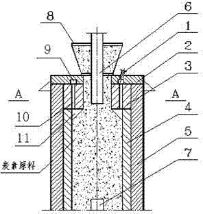
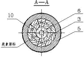
[0015] Embodiment of the present invention: the feeding port of the furnace cover 2 is connected to the feeding hopper 8, the upper electrode 6 is arranged in the center of the feeding hopper 8 and inserted into the carbon raw material under the furnace cover 2, and the lower electrode 7 is arranged at the lower part of the furnace body; The outer periphery of the lower part of the cover 2 is a refractory material lining 5, and within the refractory material lining 5 are an upper carbon lining 3 and a lower carbon lining 4, the thickness of the upper carbon lining 3 is greater than the thickness of the lower carbon lining 4, and the upper carbon lining The upper surface of the lining 3 is attached to the lower surface of the furnace cover 2; an exhaust hole 10 is provided in the upper carbon lining 3, and an annular exhaust channel 9 is provided at the bottom of the furnace cover 2, and the exhaust hole 10 and the annular exhaust channel 9 are connected; one or more exhaust pip...


PUM


Abstract

The invention discloses an electric calcining furnace for a graphite carbon material. A charging hole of a furnace cover (2) is connected with a charging hopper (8), an upper electrode (6) is arranged in the center of the charging hopper (8) and inserted into a carbon raw material below the furnace cover (2), and a lower electrode (7) is arranged on the lower part of a furnace body; a refractory material lining (5) is arranged on the periphery below the furnace cover (2), an upper carbon lining (3) and a lower carbon lining (4) are arranged in the refractory material lining (5), the upper carbon lining (3) is thicker than the lower carbon lining (4), and the upper surface of the upper carbon lining (3) is attached to the lower surface of the furnace cover (2); exhaust holes (10) are formed in the upper carbon lining (3), an annular exhaust passage (9) is arranged at the bottom of the furnace cover (2), and the exhaust holes (10) are communicated with the annular exhaust passage (9); and one or more exhaust pipes (1) are arranged on the upper part of the furnace cover (2) and connected with the annular exhaust passage (9).

Description

technical field [0001] The invention relates to an electric calciner for graphite carbon material. Background technique [0002] The upper part of the electric calciner is the feeding port, and the discharging port is located at the lower part. The raw material enters the furnace from the upper hopper, and the electricity is transmitted through the upper and lower electrodes, and the resistance of the carbon raw material itself is used to generate heat, so that the raw material is preheated (low temperature section), heated (high temperature section) and cooled from top to bottom, and then discharged from the bottom Electric calciner. During the heat treatment process of carbon raw materials that basically do not contain volatile matter, sulfur and some impurities are mainly gasified at a high temperature stage above 1700 °C. The existing technology is to set a vent hole on the furnace cover. The gasified sulfur and impurities need to pass through the low-temperature secti...

Claims


Application Information

Patent Timeline
Patent Type & Authority Patents(China)
IPC IPC(8): C01B31/04C01B32/205
Inventor 谢志群彭勇
Owner GUIYANG AL-MG DESIGN & RES INST
Why Eureka
Try Eureka