Industrial fan volute

An industrial, volute technology, applied to parts of pumping devices for elastic fluids, non-variable pumps, machines/engines, etc., which can solve problems such as difficulty in drawing

Active Publication Date: 2013-06-19
RIELLO HEATING EQUIP SHANGHAI
View PDF6 Cites 2 Cited by
  • Summary
  • Abstract
  • Description
  • Claims
  • Application Information

AI Technical Summary

Problems solved by technology

[0003] However, there are great difficulties in delineating such contours

Method used


Image

  • Industrial fan volute
  • Industrial fan volute
  • Industrial fan volute

Examples


Embodiment Construction

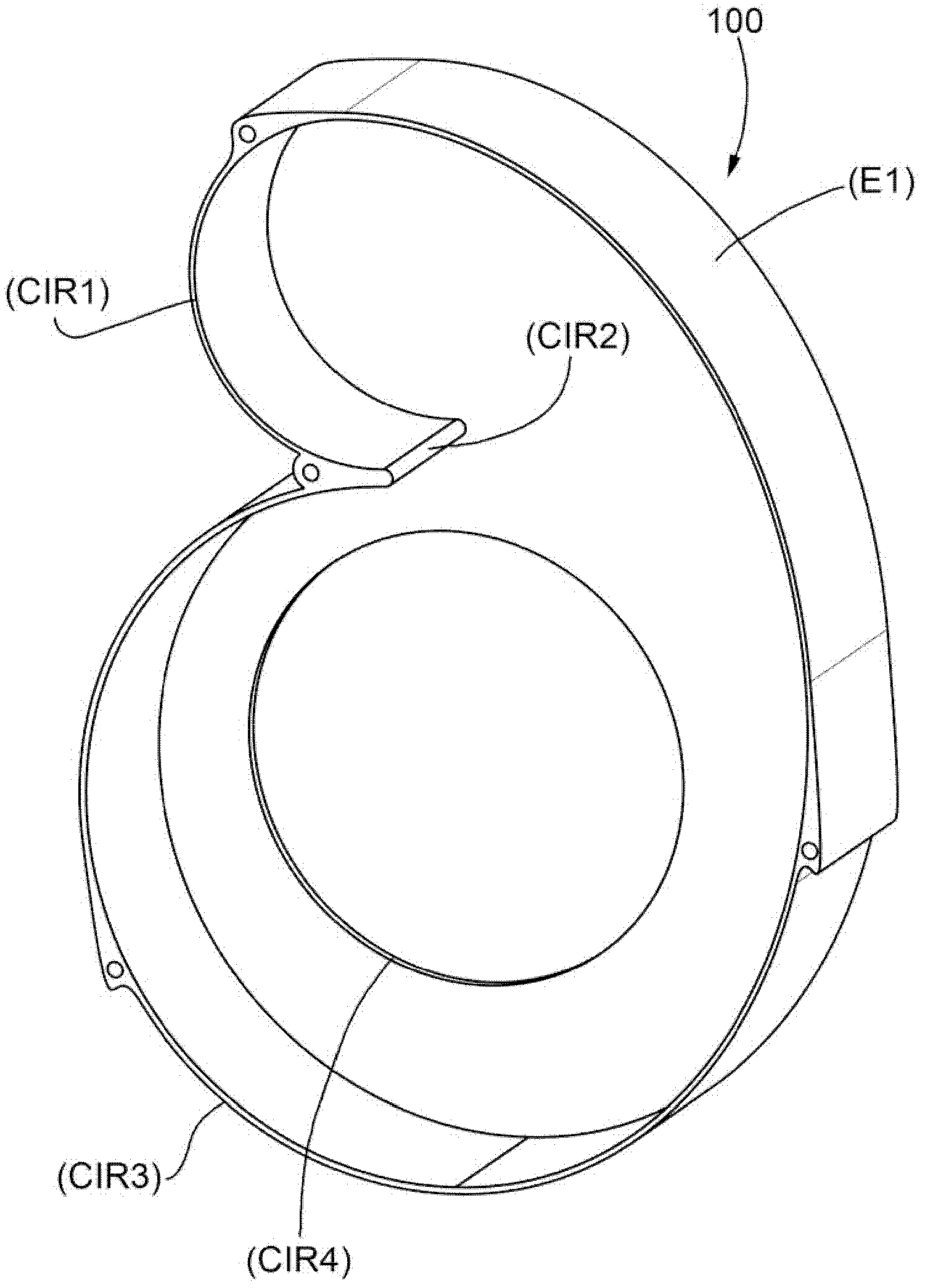
[0016] figure 1 The reference number 100 in represents generally a fan volute according to the teachings of the present invention.

[0017] In the example shown, the volute has an air inflow perpendicular to the larger circular area (as is often the case in centrifugal fans) and an air outlet perpendicular to the smaller circular area (However, this is usually not the case).

[0018] As is known from the technical literature on the subject, this design provides greater axial compactness of the volute (ie, perpendicular to the circular area).

[0019] As explained in more detail below, the hole in the bottom of the volute at the larger circular area serves as a mount for components of the electric motor that powers the fan wheel.

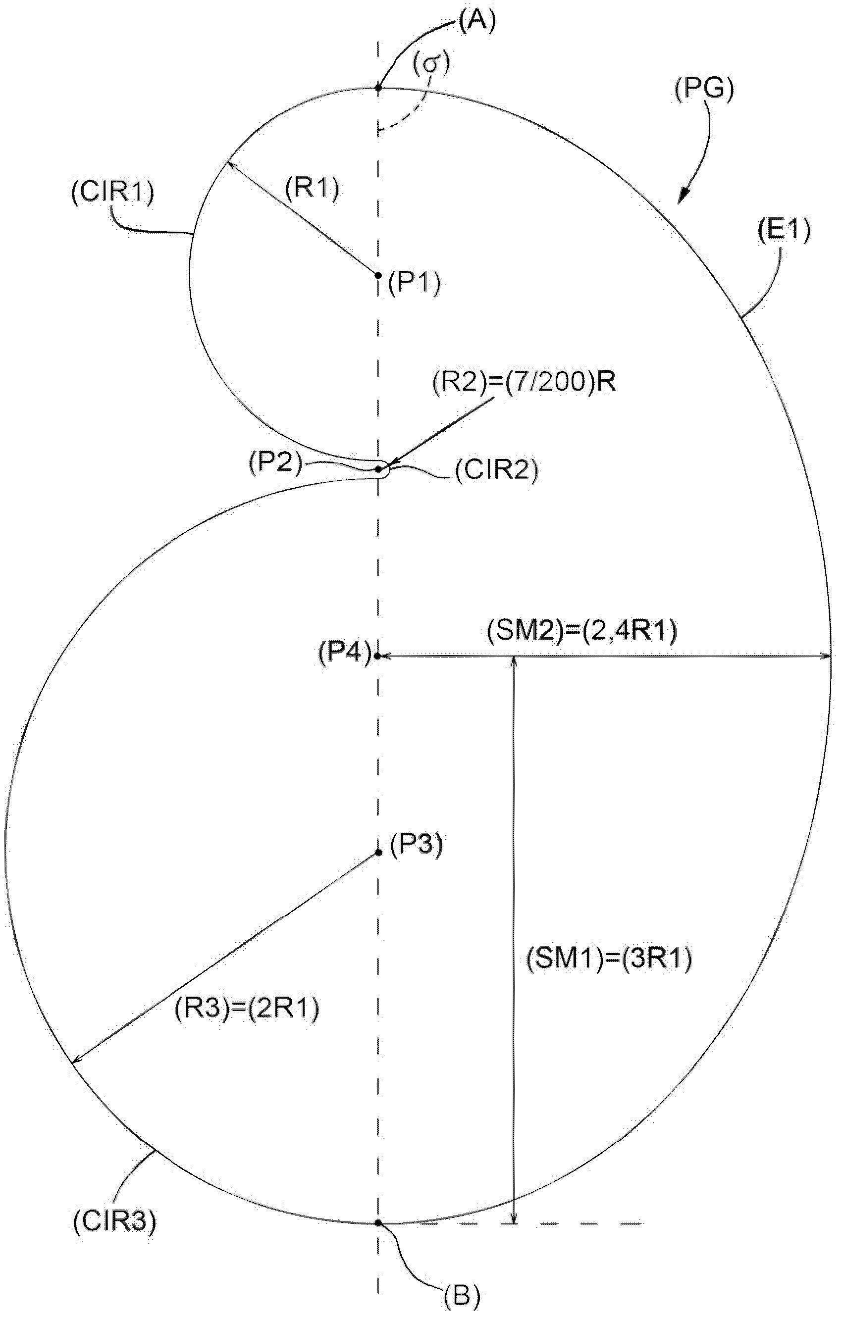
[0020] figure 2 A plan view of the geometric profile (PG) of the volute 100 is shown.

[0021] Geometric Profiles (PG) include:

[0022] - a semicircle (CIR1), having a center (P1) and a radius (R1), said semicircle defining a circular air outl...


PUM


Abstract

An industrial fan volute (100) is characterized in that the geometric outline (PG) of the industrial fan volute comprises a first semi-circle (CIR1) which is provided with a center of a circle (P1) and a radius (R1), a second semi-circle (CIR2) which is provided with a center of a circle (P2) and a radius (R2)=(7/200)(R1), a third semi-circle (CIR3) which is provided with a center of a circle (P3) and a radius (R3)=(2R1), and a semi-ellipse (E1) which is provided with a center (P4), an arc (AB), a main semi-axis (SM1)=(3R1) and an inferior semi-axis (SM2)=(2.4R1). The first semi-circle defines a round air outlet area, the second semi-circle defines an appearance of a 'cutwater' for parting airflow internally, and the third semi-circle defines a round area for confining the airflow in an impeller area.

Description

technical field [0001] The present invention relates to a volute for a fan used in industrial applications such as burner ventilation systems. Background technique [0002] As is known, the profile of a fan volute is defined by a radius-increasing, eg linear or logarithmic equation connecting the center point and the profile generating point. [0003] However, there are great difficulties in delineating such profiles. Contents of the invention [0004] It is therefore an object of the present invention to provide a fan volute which is cheap and easy to manufacture. [0005] According to the present invention, an industrial fan volute is provided, wherein the geometric profile of the volute includes: a first semicircle CIR1 having a center P1 and a radius R1, the first semicircle defining a circular air outlet area; The second semicircle CIR2, having the center P2 and the radius R2=7 / 200R1, said second semicircle defines the shape of the "cutwater" that divides the airflo...

Claims


Application Information

Patent Timeline
Patent Type & Authority Applications(China)
IPC IPC(8): F04D29/42
Inventor 詹卢卡·阿根蒂尼福斯托·达勒梅塞
Owner RIELLO HEATING EQUIP SHANGHAI
Why Eureka
Try Eureka