
Small underwater light-emitting diode (LED) lighting device

A technology of LED lighting and small water, which is applied in lighting devices, fixed lighting devices, components of lighting devices, etc., can solve the special needs of working voltage, power consumption, electrical interface robots, flexible matching, and has certain dimensions for installation and fixation. The requirements of the underwater robot system are not conducive to the popularization and use of underwater robot systems, so as to achieve the effects of convenient maintenance and expansion, improved energy utilization, good scalability and adaptability

Inactive Publication Date: 2013-06-19
SHENYANG INST OF AUTOMATION - CHINESE ACAD OF SCI
View PDF3 Cites 4 Cited by
  • Summary
  • Abstract
  • Description
  • Claims
  • Application Information

AI Technical Summary

Problems solved by technology

At present, some professional underwater lighting lamps have appeared on the market, but the models of these lighting lamps are relatively fixed, and their working voltage, power consumption and other indicators, as well as the electrical interface and mechanical seal interface form cannot be flexibly matched with the special needs of robots; in addition , usually these professional underwater lights are more expensive, and their dimensions have certain requirements for installation and fixing, which is not conducive to the popularization and use of low-cost, miniaturized underwater robot systems

Method used


Image

  • Small underwater light-emitting diode (LED) lighting device
  • Small underwater light-emitting diode (LED) lighting device
  • Small underwater light-emitting diode (LED) lighting device

Examples


Embodiment Construction

[0020] The present invention will be described in further detail below in conjunction with the accompanying drawings.

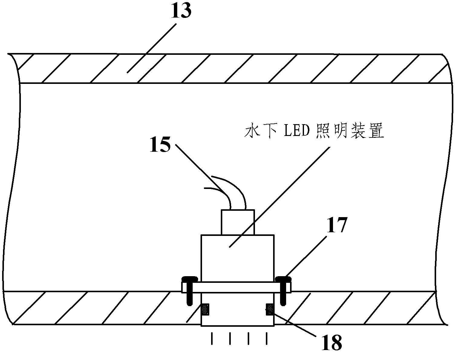
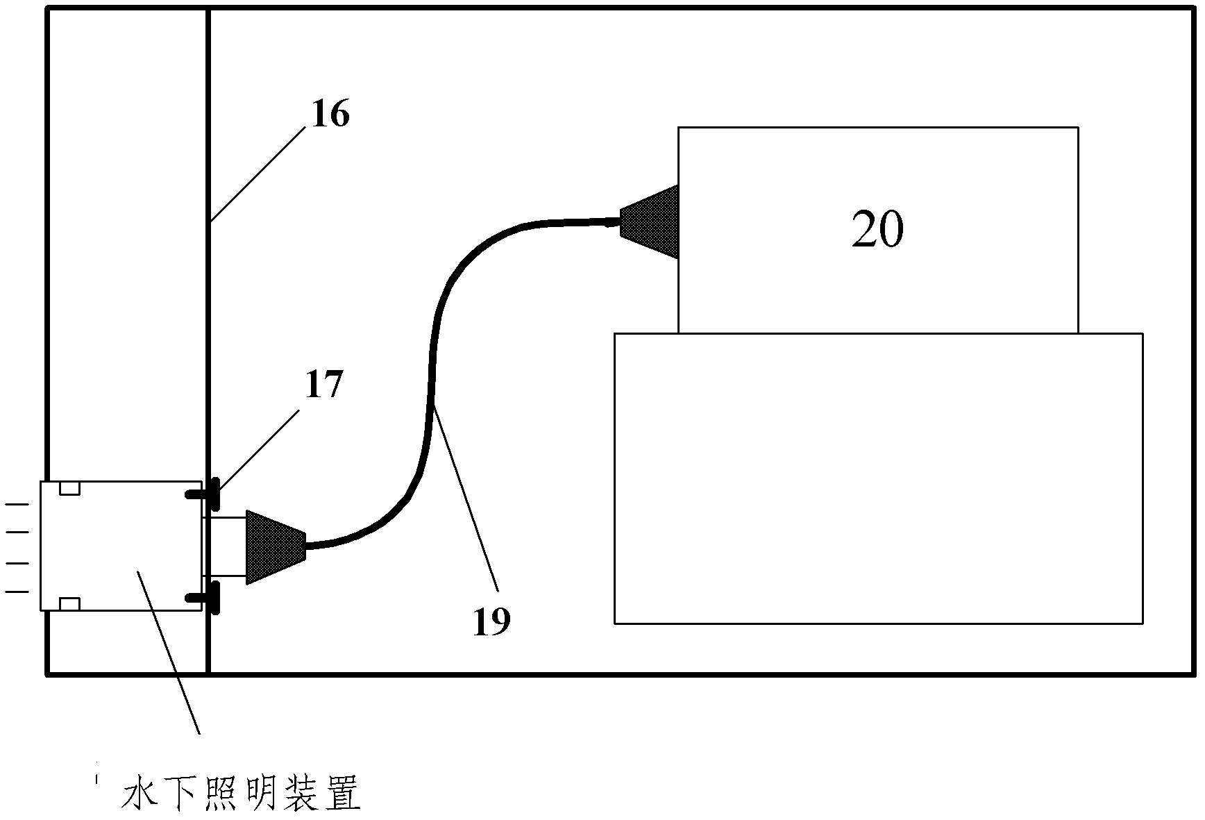
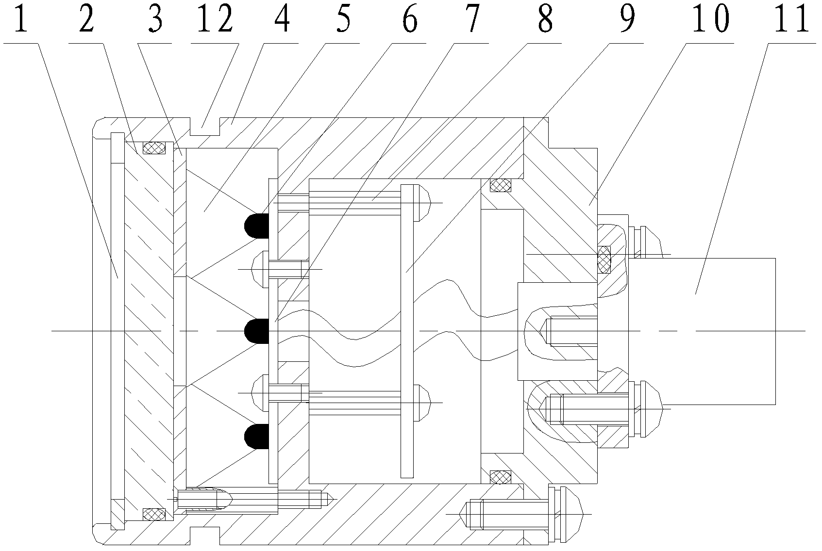
[0021] Such as Figure 3-5 As shown, the present invention includes a perspective window 2, a sealing cover 4, a condenser lens 5, an LED illuminant 6, a heat dissipation plate 7, a control panel 9, a sealing tail cover 10 and a watertight connector base 11, wherein the heat dissipation plate 7 and the control panel 9 are respectively Installed in the cabin of the sealing cover 4, the cooling plate 7 is fixedly connected in the cabin of the sealing cover 4 by screws, the control panel 9 is installed in the cabin of the sealing cover 4 by the stud 8, and the control panel 9 is fixed on one end of the stud 8 , the other end of the stud 8 utilizes threads to be fixedly connected in the cabin of the sealing cover 4; the control panel 9 of the present invention is a prior art. A plurality of LED light emitters 6 are evenly distributed on one side surface of the h...


PUM


Abstract

The invention relates to an underwater lighting device, in particular to a small underwater light-emitting diode (LED) lighting device for an underwater robot. The small underwater LED lighting device comprises a perspective window, a sealing cover, collecting lenses, LED luminous bodies, a radiation plate, a control plate, a sealing tail cover and a watertight connector assembly base, wherein the radiation plate and the control plate are respectively installed in a cabinet body of the sealing cover, a plurality of LED luminous bodies are evenly distributed on the surface of one side of the radiation plate, the collecting lenses are sleeved on protruded portions of the LED luminous bodies, the perspective window is in sealing connection with the inner wall of one end of the sealing cover and is positioned on the outer sides of the collecting lenses, the control plate is arranged on the other side of the radiation plate and electrically connected with the LED luminous bodies, the sealing tail cover is in sealing connection with the other end of the sealing cover, and the watertight connector assembly base is in sealing connection with an end face of the outer side of the sealing tail cover and electrically connected with the control plate. The small underwater LED lighting device ahs the advantages of being compact in structure, reliable in sealing, flexible and controllable, flexible to install and fix and suitable for different types and different requirements of underwater robots.

Description

technical field [0001] The invention relates to an underwater lighting device, in particular to a small underwater LED lighting device which can be used for an underwater robot. Background technique [0002] Underwater observation and underwater operation are the two main tasks of underwater robots. Under the conditions of near the water surface and clear water quality, the robot can perform certain tasks with the help of external light sources (such as sunlight, searchlights, etc.) penetrated from the water surface. mission tasks. However, under normal circumstances, underwater robots perform tasks in a relatively deep underwater environment with low visibility or even zero visibility. Light source cameras, video cameras, etc.), or underwater operation tools (such as underwater manipulators, etc.), all need the assistance of the lighting device carried by the robot to realize the observation, detection, identification and positioning of the operation object or accurate ope...

Claims


Application Information

Patent Timeline
IPC IPC(8): F21S8/00F21V17/12F21V17/16F21V31/00F21Y101/02F21Y115/10
Inventor 唐元贵任申真李硕李一平
Owner SHENYANG INST OF AUTOMATION - CHINESE ACAD OF SCI
Learn More