Non-contact high-power light-emitting diode (LED) junction temperature test method

A test method, non-contact technology, applied in the direction of single semiconductor device test, thermometer, measuring device, etc., can solve the problems of high sampling speed and complicated operation, and achieve the effect of easy practical use, simple operation and high measurement accuracy

Active Publication Date: 2013-06-19
SHANGHAI AVIATION ELECTRIC
View PDF5 Cites 30 Cited by
  • Summary
  • Abstract
  • Description
  • Claims
  • Application Information

AI Technical Summary

Problems solved by technology

[0006] The purpose of the present invention is to propose a non-contact high-power LED junction temperature test method, the purpose of which is to adopt a junction temperature change method different from the traditional pulse high-current junction temperature test method. It is realized by changing the working current and changing the temperature of the heat sink, so as to overcome the shortcomings of the traditional pulse large current junction temperature measurement method, which is complex in operation and requires high precision and sampling speed of the measuring instrument.

Method used


Image

  • Non-contact high-power light-emitting diode (LED) junction temperature test method
  • Non-contact high-power light-emitting diode (LED) junction temperature test method

Examples


Embodiment Construction

[0011] In order to make the technical means, creative features, objectives and effects of the present invention easy to understand, the present invention will be further elaborated below in combination with diagrams and specific implementation methods.

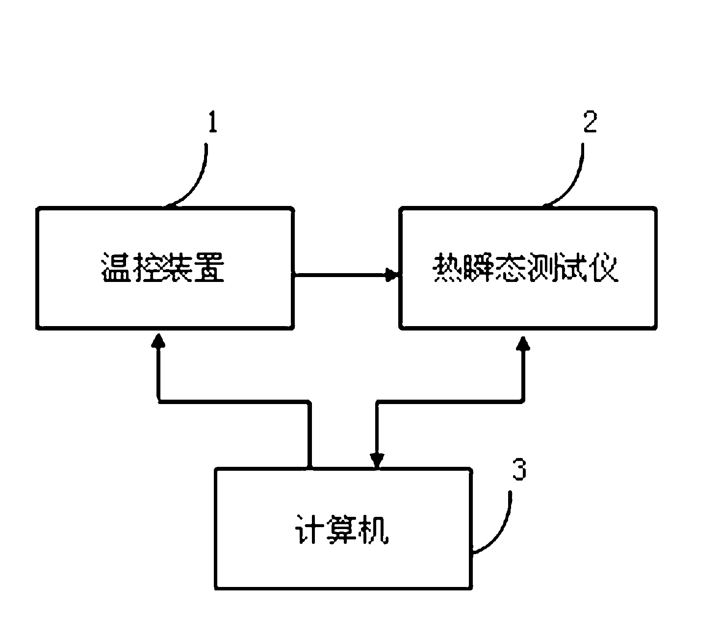
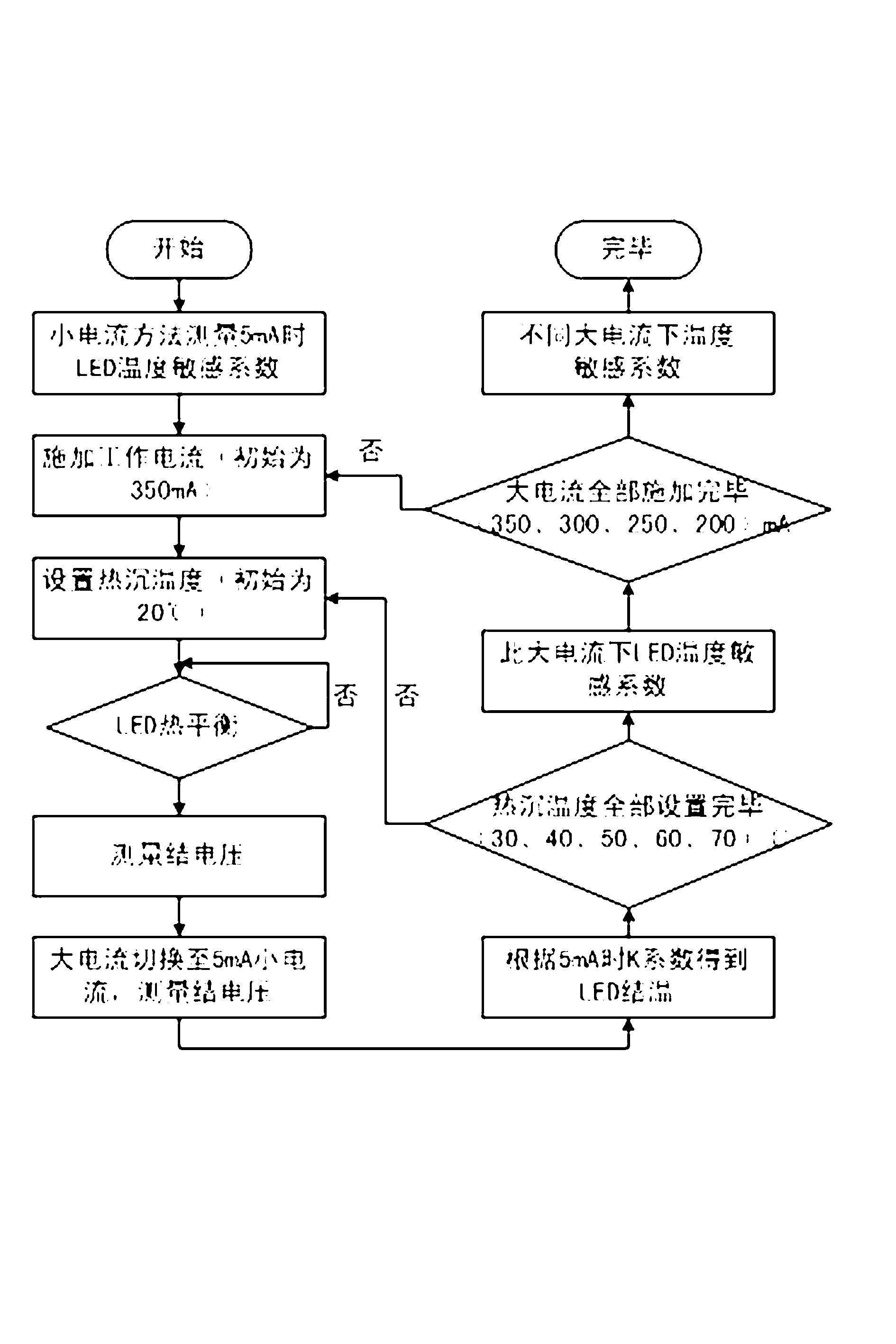
[0012] The non-contact high-power LED junction temperature testing method provided by the invention includes the measurement of K coefficient based on small current and the measurement of LED temperature sensitivity coefficient based on pulsed large current. Such as figure 1 As shown, the junction temperature measurement circuit includes a temperature control device 1 , a thermal transient tester 2 , and a personal computer 3 .

[0013] The temperature control device 1 is used to control the temperature of the heat sink in the thermal transient tester 2, the temperature control accuracy is ±0.1°C, and the temperature control range is 20°C~110°C. Thermal Transient Tester 2 is used to measure the thermal characteristics of LEDs...


PUM


Abstract

The invention relates to a non-contact high-power light-emitting diode (LED) junction temperature test method which comprises the following steps: (A) obtaining a temperature sensitivity coefficient curve of LED junction voltage along with temperature changes when a current is small, (B) providing a normal working current for an LED and measuring the LED junction voltage after a temperature is balanced, (C) rapidly switching the normal working current into a small current and measuring an LED junction temperature at the moment by using a small current junction temperature measuring method, (D) fitting LED junction temperatures and junction voltages under different heat sink temperatures and obtaining an LED temperature sensitivity coefficient under the current, (E) changing the numerical value of the normal working current and repeating B-D to obtain LED temperature sensitivity coefficients under different working currents, and (F) measuring an LED junction voltage under an actual working state and obtaining an LED junction temperature at the moment according to an LED temperature sensitivity coefficient under the working current. Compared with the existing large current junction temperature test method, the non-contact high-power LED junction temperature test method is simple in operation, high in test accuracy and easy to use in practice.

Description

technical field [0001] The invention relates to the field of lighting fixtures, in particular to a non-contact high-power LED junction temperature testing method. Background technique [0002] Due to the advantages of small size, high reliability, long life and high efficiency, LED has gradually been recognized by the market and is becoming more and more popular. It is widely used in many fields, especially in the field of semiconductor lighting. However, the junction temperature detection and heat dissipation of LED devices is a prominent problem, and it is also a difficult problem that must be solved in LED applications. As an important parameter to measure the performance of LED devices, junction temperature is the core element of reliability measurement in LED device engineering applications. Accurately measuring the junction temperature of semiconductor LEDs has important practical significance. [0003] At present, there are usually the following methods for measuring...

Claims


Application Information

Patent Timeline
Patent Type & Authority Applications(China)
IPC IPC(8): G01K11/00G01R31/26
Inventor 曾庆兵冉剑
Owner SHANGHAI AVIATION ELECTRIC
Why Eureka
Try Eureka