Real-time simulation method and real-time simulation system

A technology of real-time simulation and circuit simulation, applied in general control systems, control/regulation systems, instruments, etc., can solve the problems of unavoidable switching process, occupied resources and consumption, limited equipment resources, etc.

Active Publication Date: 2013-06-19
ZHUZHOU ELECTRIC LOCOMOTIVE CO
View PDF5 Cites 10 Cited by
  • Summary
  • Abstract
  • Description
  • Claims
  • Application Information

AI Technical Summary

Problems solved by technology

Different from the offline simulation, the HiL simulator uses a fixed-step mathematical method to run in real time, which makes the HiL simulator and the controller run asynchronously, and the switching process within the simulation step is inevitable, resulting in the loss of the switching signal of the controller, which in turn leads to There is a calculation error in the state change of the transmission system
Therefore, the processor-based Pro and FPGA-based HiL simulations are used. Although the processor-based HiL simulation can accurately calculate the system state variables with fixed sampling intervals, due to the sequential instruction execution system software and the hardware consumption of the real-time processor , the resulting wait or HiL simulation delay caused by the simulation step limit is usually much longer than the real device, and the longest delay may be longer than a simulation time step
At present, the minimum time step is about 20μs. Therefore, compared with the actual converter and motor, the additional delay caused by the operation of the processor Pro will cause a considerable error in the Hil simulation, which cannot meet the requirements of real-time simulation; An FPGA-based HiL simulation, because of limited equipment resources, long compilation and integration time, more resources and consumption, can not meet the requirements of real-time simulation

Method used


Image

  • Real-time simulation method and real-time simulation system
  • Real-time simulation method and real-time simulation system
  • Real-time simulation method and real-time simulation system

Examples


Embodiment Construction

[0047]The following will clearly and completely describe the technical solutions in the embodiments of the present invention with reference to the accompanying drawings in the embodiments of the present invention. Obviously, the described embodiments are only some, not all, embodiments of the present invention. Based on the embodiments of the present invention, all other embodiments obtained by persons of ordinary skill in the art without making creative efforts belong to the protection scope of the present invention.

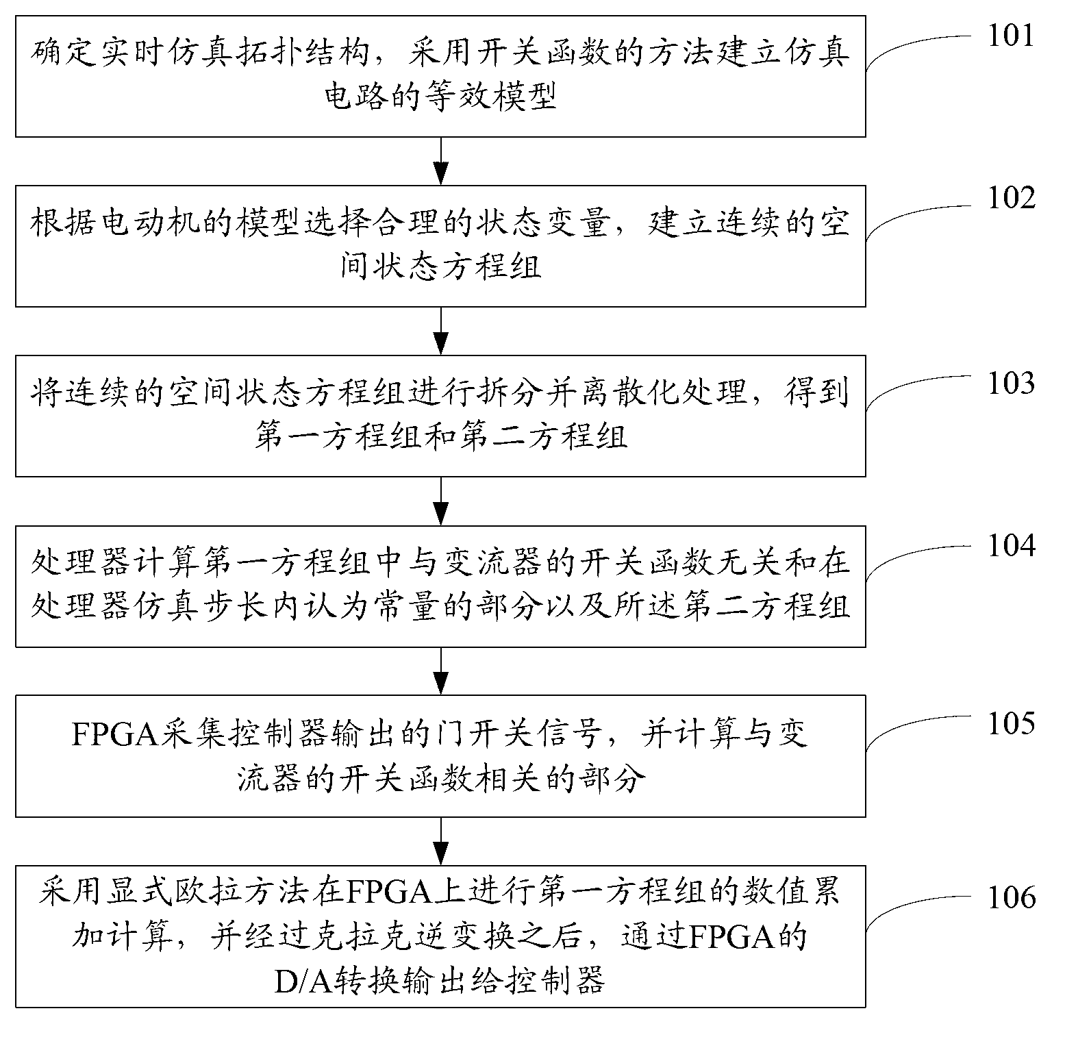
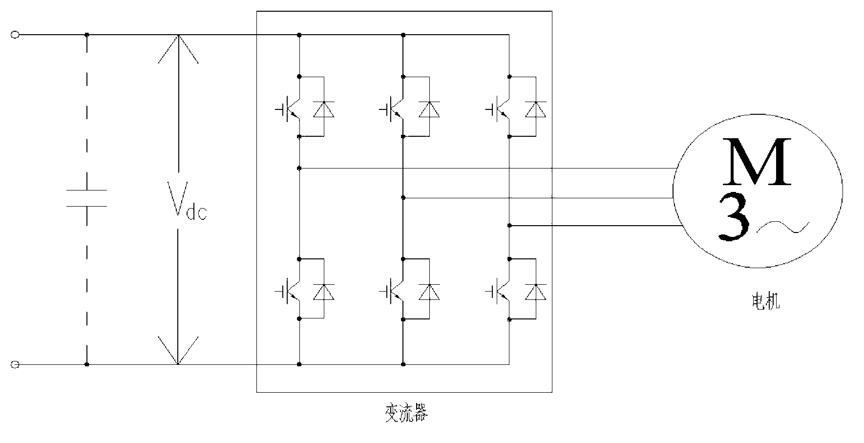
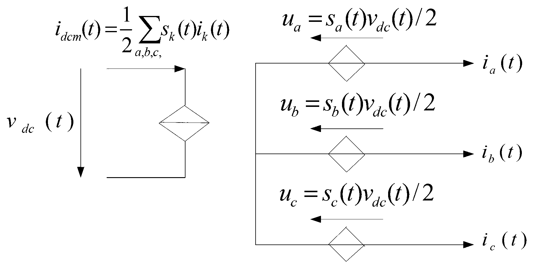
[0048] This application discloses a method and system for real-time simulation, which is suitable for AC traction drive systems and is applied to real-time simulation models composed of converters and motors. The method is based on two-level voltage source converters realized by FPGA and processors Mixed real-time simulation of circuit breaker and three-phase AC asynchronous squirrel-cage motor topology circuit, in which the multiplication operation that takes u...


PUM


Abstract

The invention discloses a real-time simulation method and a real-time simulation system which are applicable to an alternating current traction transmission and applied to a real-time simulation model comprising a converter and a motor. Hybrid real-time simulation for a two-level voltage source converter and a three-phase alternating current asynchronous squirrel-cage motor topology circuit is realized based on an FPGA (field programmable gate array) and a processor, multiplication occupying more resources and slowly changing variables needing parameter setting are operated by the processor, rapidly changing system input/output variables related to door opening and closing signals are directly accumulated by the FPGA, an I/O (input/output) channel of the FPGA is used for acquiring the door opening and closing signals inputted by the system and the variables outputted by an output system, the resources occupied by the FPGA and time delay caused by operation of the processor are maximally decreased, the advantages of operation potential of the processor and high precision of the FPGA are made full use of, and the simulation scale of the alternating current transmission locomotive/vehicle traction system is effectively expanded without increasing the cost of a simulation hardware platform.

Description

technical field [0001] The invention relates to the technical field of AC traction drive, and more specifically, relates to a real-time simulation method and system. Background technique [0002] In the field of AC traction transmission, with the increase of intelligence and complexity of power electronics and drive system controllers, real-time simulation is a simulation study in which the dynamic process of the system simulation model is exactly the same as the time course of the dynamic process of the actual system. For example: as attached figure 1 The HiL (Hardware-in-the-Loop, hardware loop) real-time simulation of the shown controller, the developed controller is the device under test, which is connected to the HiL virtual device in the same connection mode as the actual device. HiL simulation runs in real time based on high-performance processor Pro or FPGA (Field-Programmable Gate Array, Field Programmable Gate Array), which can accurately simulate the electrical c...

Claims


Application Information

Patent Timeline
Patent Type & Authority Applications(China)
IPC IPC(8): G05B17/02
Inventor 佟来生李希宁邹焕青郭婉露
Owner ZHUZHOU ELECTRIC LOCOMOTIVE CO
Why Eureka
Try Eureka