Manufacturing method of interconnect structure

A manufacturing method and interconnection structure technology, applied in semiconductor/solid-state device manufacturing, electrical components, circuits, etc., can solve the problems of reducing RC delay, small air gap, easy deposition, etc.

Active Publication Date: 2015-08-05
SEMICON MFG INT (SHANGHAI) CORP
View PDF9 Cites 0 Cited by
  • Summary
  • Abstract
  • Description
  • Claims
  • Application Information

AI Technical Summary

Problems solved by technology

[0006] However, when forming the through hole, it is easy to form a through hole with a large top horizontal dimension, which makes the dielectric material easy to deposit on the bottom and sidewall of the through hole, thereby filling the through hole, but failing to timely fill all the through holes. The above vias are sealed, which makes the air gap formed small, which is not conducive to reducing RC delay

Method used


Image

  • Manufacturing method of interconnect structure
  • Manufacturing method of interconnect structure
  • Manufacturing method of interconnect structure

Examples


Embodiment Construction

[0028] In the following description, numerous specific details are set forth in order to provide a thorough understanding of the present invention. However, the present invention can be implemented in many other ways different from those described here, and those skilled in the art can make similar extensions without violating the connotation of the present invention, so the present invention is not limited by the specific implementations disclosed below.

[0029] Secondly, the present invention is described in detail by means of schematic diagrams. When describing the embodiments of the present invention in detail, for convenience of explanation, the schematic diagrams are only examples, which should not limit the protection scope of the present invention.

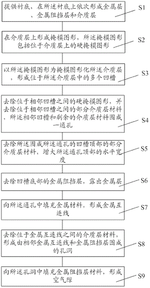
[0030] In order to solve the problems of the prior art, the present invention provides a method for manufacturing an interconnection structure, referring to figure 2 , which shows a schematic flow chart of an embodiment ...


PUM


Abstract

The invention provides a manufacturing method of an interconnection structure. The manufacturing method comprises: supplying a substrate, forming a metal layer, a metal barrier layer and a medium layer successively on the substrate; forming a plurality of grooves in the medium layer; removing parts of medium layer materials at tops of the grooves, enlarging the horizontal widths of the tops of the grooves; removing the metal barrier layer at the bottoms of the grooves, exposing the metal layer; filling metal materials in the grooves to form metal interconnection lines; removing medium layer materials located between the metal interconnection lines, forming holes surrounded by adjacent metal interconnection lines and the metal barrier layer; filling metal barrier layer materials in the holes to form air gaps. The manufacturing method enlarges sizes of the air gaps in the interconnection structure and can improve electrical properties of semiconductor devices of the interconnection structure.

Description

technical field [0001] The invention relates to the technical field of semiconductors, in particular to a method for manufacturing an interconnection structure. Background technique [0002] One of the challenges encountered in the field of integrated circuit design and manufacturing today is how to reduce the RC delay (Resistive Capacitive delay) of signal transmission. In this regard, one method that the current technology has adopted is to replace the aluminum metal layer with a copper metal layer to reduce the metal delay. Layer series resistance; Another method is to reduce the parasitic capacitance between metal layers, which can be achieved by constructing porous (Porous) low dielectric constant (Low k) material or air gap (Air gap) in the dielectric layer between metal layers. Gap) to achieve. [0003] The prior art discloses a method of fabricating self-aligned nanocolumnar air gaps and the structures fabricated therefrom, such as figure 1 shown. Wherein, the die...

Claims


Application Information

Patent Timeline
Patent Type & Authority Patents(China)
IPC IPC(8): H01L21/768
Inventor 周鸣
Owner SEMICON MFG INT (SHANGHAI) CORP
Why Eureka
Try Eureka