Dc-dc converter

a converter and converter technology, applied in the direction of electrical apparatus casings/cabinets/drawers, process and machine control, instruments, etc., can solve the problems of inability to fully realize the coupling, and inability to achieve complete coupling, etc., to achieve the effect of reducing the pressure drop width, enhancing the cooling efficiency, and large heating valu

Active Publication Date: 2019-08-15
LG INNOTEK CO LTD
View PDF0 Cites 11 Cited by
  • Summary
  • Abstract
  • Description
  • Claims
  • Application Information

AI Technical Summary

Benefits of technology

[0053]In the DC-DC converter of the first embodiment, since the difference in the area of the vertical cross section in all portions of the flow path is within 10%, the flow rate of the cooling material is increased and the pressure drop width is reduced, thereby enhancing the cooling efficiency. Further, electronic components (for example, a diode module) having a large heating value and a large area can be intensively cooled by matching with an expanding portion (a portion having a large horizontal width and a thin vertical width) of the flow path.
[0054]The second embodiment provides a DC-DC converter wherein a secondary coil, an inductor coil, and a bus bar are integrally formed by a casting process, thereby enhancing the conversion efficiency thereof, and comprising a coil module having a compact structure with reduced weight.
[0055]According to the third embodiment, the size of an electronic component assembly and a converter can be reduced by increasing the mounting density of the elements in the same space by stacking of a main board and an auxiliary board. Furthermore, by mounting an active element having a high heating value on the auxiliary board directly contacting the cooling plate, the cooling efficiency can be increased.

Problems solved by technology

However, such a manufacturing process is too complicated, and further, during bolt-coupling, there is a problem in that the coupling may be incomplete or a gap may be induced due to the warping of the material and the like.
In particular, the gaps between the secondary coil and the inductor coil, and the inductor coil and the bus bar cause problems such as heat generation due to an increase in contact resistance as well as deterioration in electrical characteristics.
In addition, since the secondary coil, the inductor coil, and the bus bar are independently manufactured as a single member, there is a problem in that the size and the weight of the DC-DC converter increase.

Method used


Image

  • Dc-dc converter
  • Dc-dc converter
  • Dc-dc converter

Examples


first embodiment

[0078]Hereinafter, “vertical direction” may mean upward and / or downward direction, and “horizontal direction” may mean any one of directions on a plane perpendicular to “vertical direction.” The “vertical direction” may be the horizontal width direction of the flow path 200, and the “horizontal direction” may be the horizontal width direction of the flow path 200. The “vertical cross section” may mean a cross section perpendicular to the moving direction of the cooling material, and the “horizontal cross section” may be a cross section perpendicular to the “vertical cross section.”

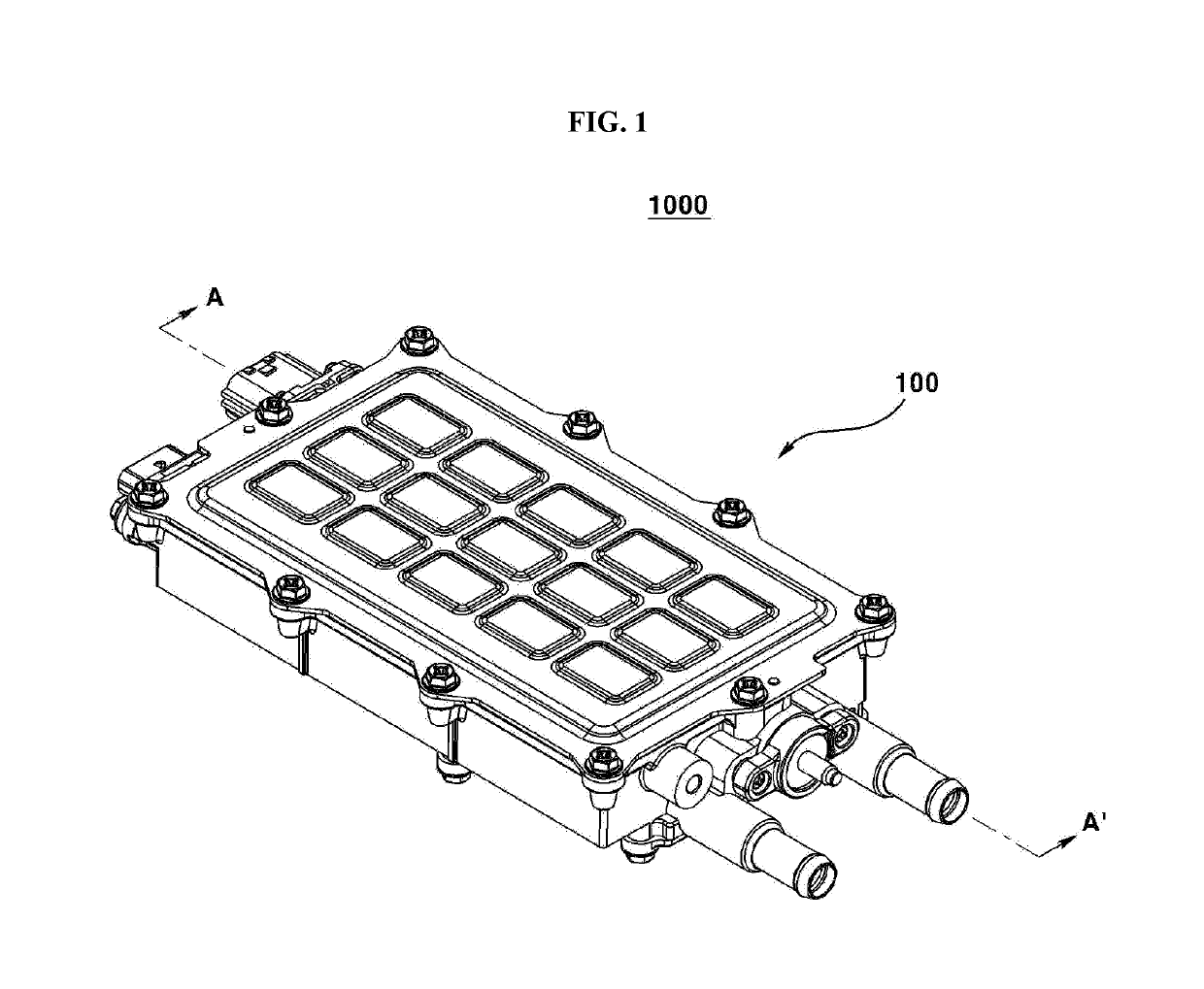
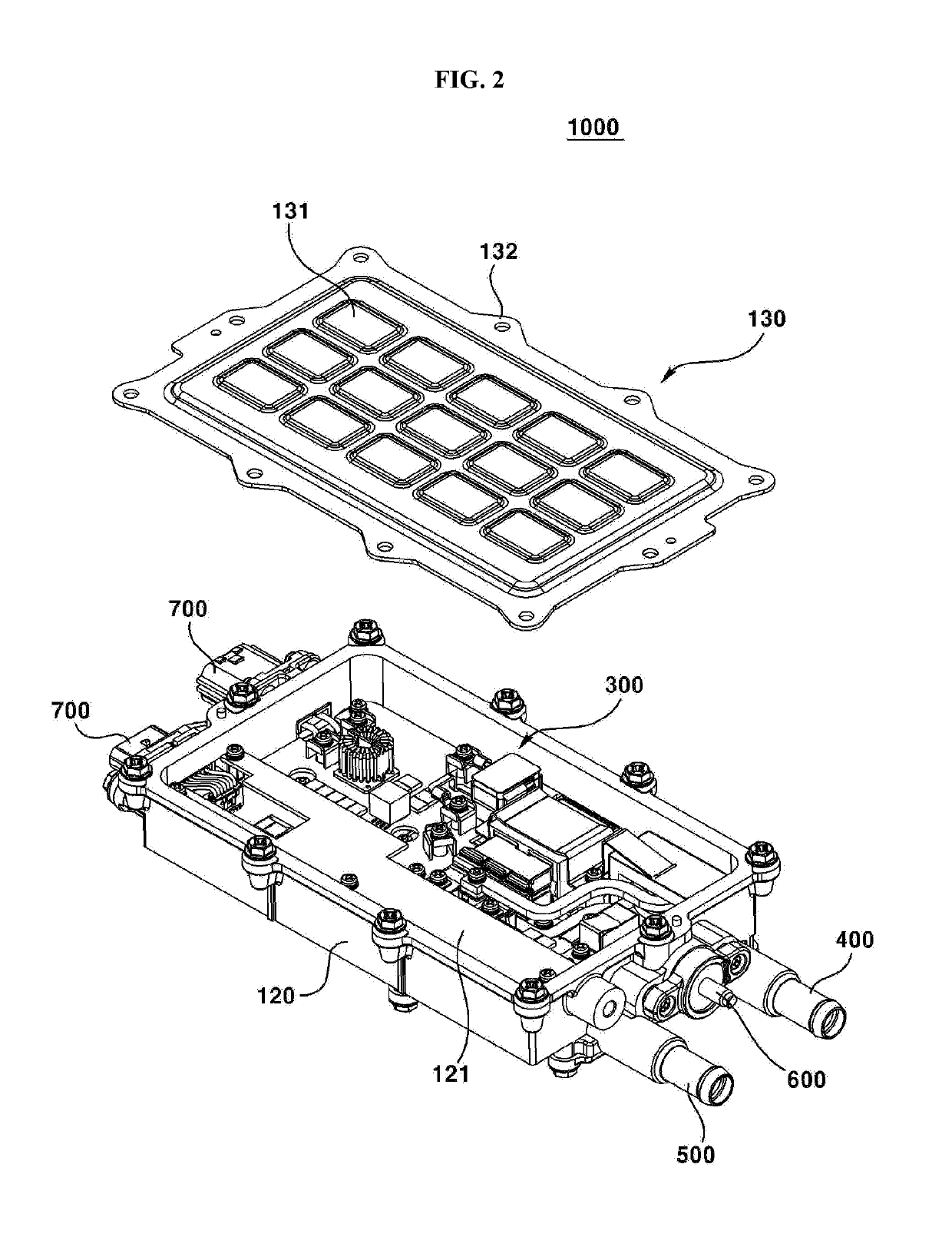
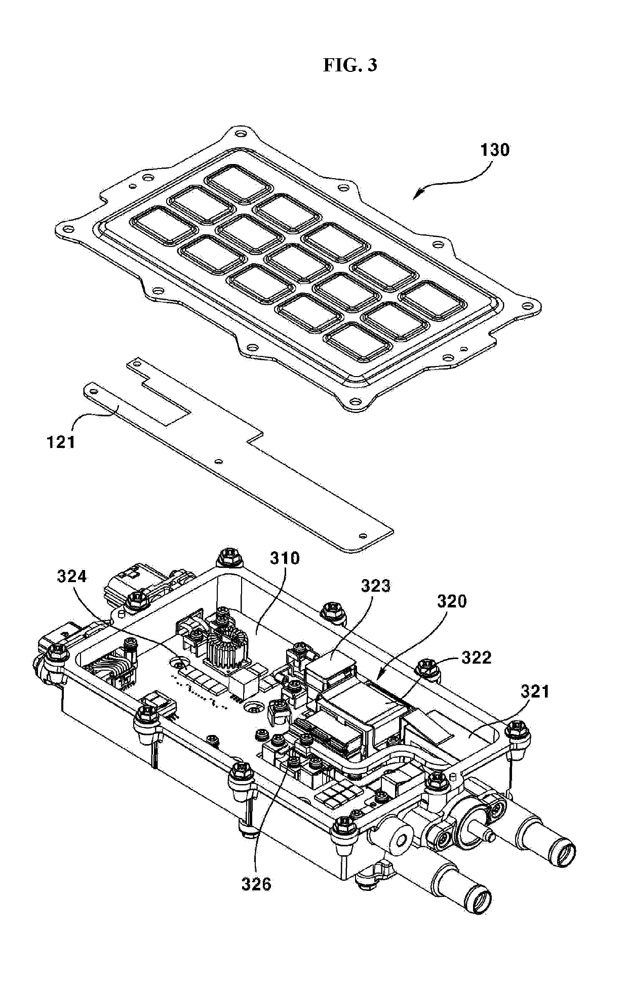
[0079]Hereinafter, a DC-DC converter 1 of the first embodiment will be described with reference to the drawings. FIG. 1 is a perspective view of a DC-DC converter of the first embodiment viewed from above; FIG. 2 is a perspective view of the DC-DC converter of the first embodiment wherein the upper cover is disassembled; FIG. 3 is a perspective view of the DC-DC converter of the first embodiment wherein th...

second embodiment

[0134]Hereinafter, a DC-DC converter 2001 according to a comparative example of the present second embodiment will be described with reference to the drawings. FIG. 10 is a perspective view illustrating a DC-DC converter of a comparative example of the second embodiment.

[0135]The DC-DC converter 2001 of the present comparative embodiment may be a DC-DC converter used in a vehicle. For example, the DC-DC converter 1000 may play the role of receiving an electric current from an external power supply device (such as a lithium ion battery), boosting or lowering a voltage, supplying the voltage to an external electronic device (such as a motor), and thereby controlling the number of revolutions of a motor and the like. The DC-DC converter 2001 may comprise a case 2010, a conversion unit 2020, an inductor unit 2030, a bus bar (not shown), and an external terminal 2050.

[0136]The case 2010 may be an external member of the DC-DC converter 2001. In the case 2001, an internal space is formed t...

third embodiment

[0184]Hereinafter, the DC-DC converter 3001 of the third embodiment will be described with reference to the drawings. FIG. 16 is a perspective view illustrating the DC-DC converter of the third embodiment with the first cover removed; FIG. 17 is a cut-away perspective view illustrating the DC-DC converter of the third embodiment; FIG. 18 is a cross sectional conceptual view illustrating a main board, an auxiliary board and a cooling plate of the DC-DC converter of the third embodiment; and FIG. 19 is a conceptual diagram illustrating a signal leg of the DC-DC converter of the third embodiment.

[0185]A DC-DC converter 3001 of the third embodiment may be a DC-DC converter used in a vehicle. For example, the DC-DC converter 1000 may play the role of receiving an electric current from an external power supply device (such as a lithium ion battery), boosting or lowering a voltage, supplying the voltage to an external electronic device (such as a motor), and thereby controlling the number ...


PUM


Abstract

The present embodiment relates to a DC-DC converter comprising: a housing; a plurality of electronic components disposed inside the housing; and a flow path disposed on a lower plate of the housing. The flow path comprises an expanding portion. The horizontal width of the expanding portion is greater than the horizontal width of a flow path on the front end of the expanding portion, and the vertical width of the expanding portion is less than the vertical width of the flow path on the front end of the expanding portion. The differential between the part wherein the surface area of the vertical cross section of the flow path is the biggest and the part wherein the surface area of the vertical cross section of the flow path is the smallest is 10% or less.

Description

TECHNICAL FIELD[0001]The present exemplary embodiment relates to a DC-DC converter.BACKGROUND ART[0002]The following description provides background information for the present embodiment and does not describe the prior art.[0003]With the emergence of environmentally friendly vehicles using electric power, it is required to reduce the weight and size of electric parts for vehicles. A DC-DC (direct current to direct current) converter for a vehicle is a device for controlling a DC voltage in a vehicle.[0004]Particularly, in an electric vehicle, it plays the role of changing voltage of a current generated in a motor so as to supply to a battery. In addition, when the electric vehicle is driving down an inclined road, the motor serves as a generator to charge the battery. In this case, the voltage of the electric current generated by the motor is changed and supplied to the battery.[0005]Various electronic components are disposed in the DC-DC converter. It is necessary to improve the c...

Claims


Application Information

Patent Timeline
Patent Type & Authority Applications(United States)
IPC IPC(8): H02M1/32H02M3/335
CPCH02M1/32H02M3/33576H02M2001/327H05K5/00H05K7/20927H05K7/20H05K7/20272H05K7/1432H05K7/023H01F27/289H05K5/0021H01F27/28H01F41/04H05K1/02H05K1/0207H05K7/02H05K7/14H05K7/20872H02M3/003H02M1/327
Inventor KIMKIM, GEUN HONA, HYUN MINJUNG, JAE HOOBAE, SEOKYEOM, JAI HOON
Owner LG INNOTEK CO LTD
Why Eureka
Try Eureka