Rotor punching sheet for permanent magnet motor and rotor

A technology of rotor punching and permanent magnet motor, which is applied in the direction of magnetic circuit rotating parts, magnetic circuit shape/style/structure, etc., and can solve the problems of low utilization rate of permanent magnet materials, low utilization rate of permanent magnets, and large magnetic flux leakage , to achieve the effect of avoiding low utilization rate, reducing invalid magnetic flux leakage and improving mechanical strength

Inactive Publication Date: 2013-06-19
安徽明腾永磁机电设备有限公司
View PDF10 Cites 3 Cited by
  • Summary
  • Abstract
  • Description
  • Claims
  • Application Information

AI Technical Summary

Problems solved by technology

The disadvantage of the built-in structure is: because the permanent magnet is inside the rotor, the magnetic flux leakage is large, and the utilization rate of the permanent magnet is low. Corresponding magnetic isolation measures must be taken to limit the magnetic flux leakage
The disadvantage of this shape of the rotor punch is that since there is a magnetic isolation bridge 21 in each "L" shaped sub magnetic steel slot, and there is also a magnetic isolation bridge 22 between two adjacent transverse slots 26, due to Excessive magnetic isolation bridges cause magnetic flux leakage and low utilization rate of permanent magnetic materials

Method used


Image

  • Rotor punching sheet for permanent magnet motor and rotor
  • Rotor punching sheet for permanent magnet motor and rotor
  • Rotor punching sheet for permanent magnet motor and rotor

Examples


Embodiment Construction

[0012] The present invention will be described in further detail below in conjunction with the accompanying drawings and specific embodiments, but not as a limitation of the present invention.

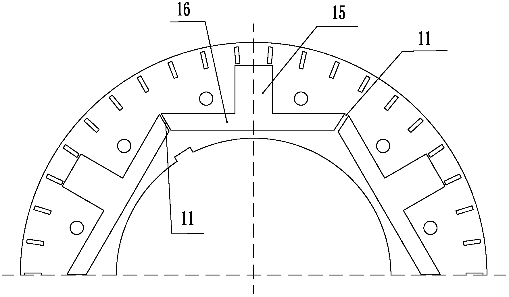
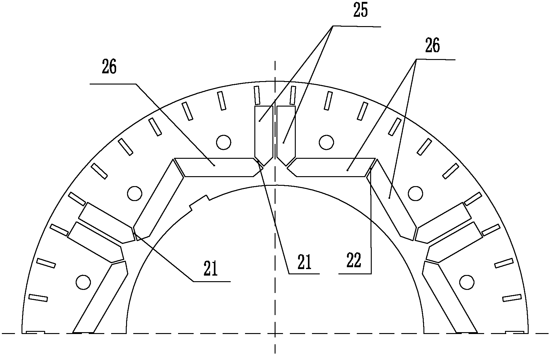
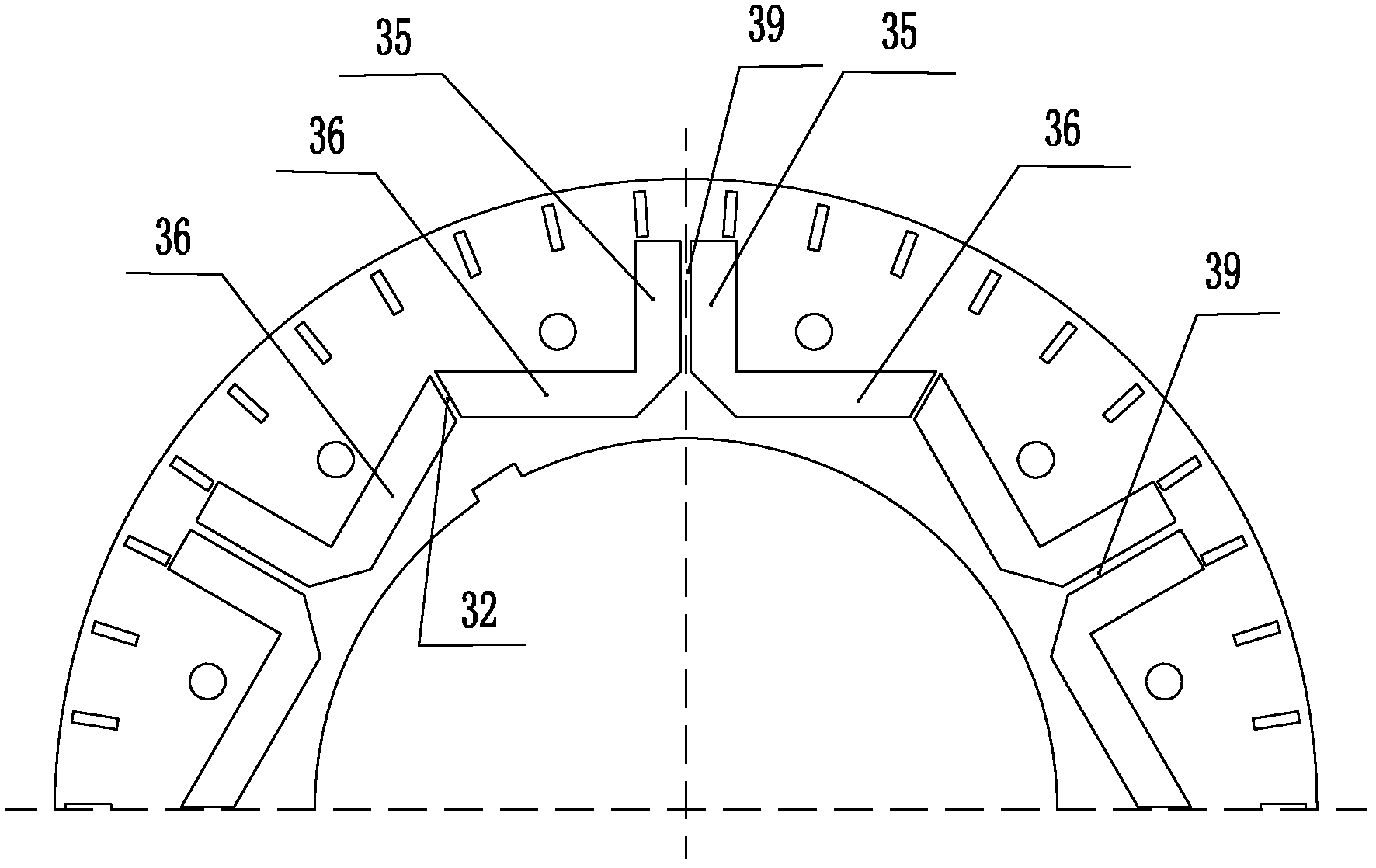
[0013] Such as image 3 As shown, the rotor punching plate used for the permanent magnet motor of the embodiment of the present invention includes a plurality of identical magnetic steel slots, and each magnetic steel slot includes a radial groove 35 arranged along the radial direction of the rotor punching plate and perpendicular to The transverse groove 36 of the radial groove 35, the end of the radial groove 35 is connected with the middle part of the transverse groove 36 and communicated; the radial groove 35 is provided with a connecting part 39 along the radial direction of the rotor punching piece, and the connecting part 39 The through radial groove 35 divides the magnet steel groove into two "L" shaped sub magnet steel grooves, and the radial part of each "L" shaped sub magnet...


PUM


Abstract

The invention discloses a rotor punching sheet for a permanent magnet motor and a rotor which is formed by a plurality of the rotor punching sheets being pressed in an overlapping mode. The rotor sheet for the permanent magnet motor comprises a plurality of magnetic steel grooves which are the same. Each magnetic steel groove comprises an axial groove which is formed along the axial direction of the rotor punching sheet and a horizontal groove which is vertical to the axial groove, an end portion of each axial groove is connected and communicated with the middle portion of a horizontal groove, a connecting portion is arranged inside each axial groove along the axial direction of the rotor punching sheet, each connecting portion penetrates through each axial groove to divide each magnetic steel groove into two L-shaped auxiliary magnetic steel grooves, and the axial part of each L-shaped auxiliary magnetic steel groove is communicated with the horizontal part of each L-shaped auxiliary magnetic steel groove. Through the method of changing the shapes of the magnetic steel grooves, the number of magnetism insulating bridges is reduced, useless magnetic flux leakage is lowered, the phenomenon that use ratio of permanent magnet materials is low due to the fact that flow of magnetic flux leakage of a permanent magnet is large is avoided, and mechanical strength of the rotor punching sheet is also improved through groove division processing of the magnetic steel grooves.

Description

technical field [0001] The invention belongs to the technical field of motors, in particular to a rotor punch and a rotor for permanent magnet motors. Background technique [0002] Asynchronous start permanent magnet synchronous motor usually adopts built-in rotor structure. In the built-in rotor structure, the permanent magnet is located in the magnetic steel groove opened in the iron core. Usually, the reluctance of the quadrature axis is smaller than the reluctance of the direct axis. Moment density; the cage-shaped rotor directly faces the air gap, and the starting performance is good. The disadvantage of the built-in structure is: since the permanent magnet is inside the rotor, the magnetic flux leakage is large, and the utilization rate of the permanent magnet is low. Corresponding magnetic isolation measures must be taken to limit the magnetic flux leakage. The commonly used magnetic isolation measure is to set a magnetic isolation bridge between the magnetic steel ...

Claims


Application Information

Patent Timeline
Patent Type & Authority Applications(China)
IPC IPC(8): H02K1/27
Inventor 张桂林梅浩东
Owner 安徽明腾永磁机电设备有限公司
Why Eureka
Try Eureka