Slush pump assembly

A mud pump and assembly technology, applied in the direction of pumps, pump components, variable displacement pump components, etc., can solve the problems of easy wear, fast reciprocating frequency, short piston life, etc., achieve high pump pressure, avoid long-term wear and tear, The effect of pressure stabilization

Inactive Publication Date: 2013-06-26
熊彪
View PDF0 Cites 2 Cited by
  • Summary
  • Abstract
  • Description
  • Claims
  • Application Information

AI Technical Summary

Problems solved by technology

[0002] The mud pumps in the prior art are mechanically driven by gears, which have the disadvan

Method used


Image

  • Slush pump assembly
  • Slush pump assembly
  • Slush pump assembly

Examples


Embodiment Construction

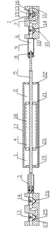
[0022] Such as figure 1 As shown in -3, the present invention comprises a group of working system 1, and working system 1 comprises power end 2 and hydraulic power end 3, and power end 2 is linear reciprocating motor 4, and the two ends of the mover shaft 5 of linear reciprocating motor 4 are connected respectively With liquid end 3.

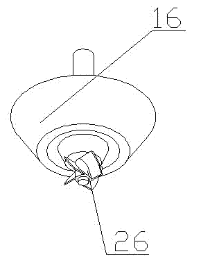
[0023] The liquid end 3 includes a piston cylinder 6 and a valve box 7 arranged at the end of the mover shaft 5, the piston cylinder 6 includes a piston 8 and a cylinder liner 9, the piston 8 is connected to the end of the mover shaft 5, and the piston 8 is set in the cylinder In the sleeve 9; the valve box 7 is provided with a liquid inlet 10, a liquid outlet 11, a suction port 12 and a liquid inlet check valve 14 and a liquid outlet check valve 13 arranged in the valve box 7, and the suction port 12 is connected to the The rodless cavity of the piston cylinder 6 is sealed and communicated. The liquid inlet check valve 14 and the liquid outlet...


PUM


Abstract

The invention provides a slush pump assembly and relates to the field of hydraulic pumps. The slush pump assembly comprises at least one group of working systems, wherein each group of working systems consists of a power end and hydraulic ends, the power end is a linear reciprocating motor, and both ends of an active cell shaft of the linear reciprocating motor are respectively connected with the hydraulic ends. The slush pump assembly is a front and rear double fluid end. When a motor conducts front-end motion, a motor shaft simultaneously drives a front double piston and a rear double piston to conduct reciprocating motion, so that a cylinder is extracted, and simultaneously the other cylinder discharges pressure. After multiple cylinders are connected in parallel, a position of a piston is adjusted, and fluid drainage capacity can be achieved constantly. Multiple pumps are connected in parallel to reach large discharge capacity in parallel according to requirements.

Description

technical field [0001] The invention relates to the field of liquid pumps, in particular to a multi-cylinder mud pump powered by a linear reciprocating motor for oil drilling. Background technique [0002] The mud pumps in the prior art are mechanically driven by gears, which have the disadvantages of short stroke, short piston life, fast reciprocating frequency, and easy wear and tear. Contents of the invention [0003] The object of the present invention is to provide a mud pump system assembly with a linear reciprocating motor as the power end, double hydraulic ends at the front and rear, multiple parallel connection, long stroke, long piston life, adjustable stroke, pressure and displacement. [0004] The technical solution for achieving the above purpose is: a mud pump assembly, characterized in that it includes at least one set of working systems, each set of working systems includes a power end and a hydraulic end, the power end is a linear reciprocating motor, and ...

Claims


Application Information

Patent Timeline
IPC IPC(8): F04B17/03F04B53/10H02K33/18
Inventor 熊彪
Owner 熊彪
Why Eureka
Try Eureka