Solar vacuum glass heat collecting tube air heat collector

An air heat collector and solar energy technology, which is applied in the field of air heating and heat collection devices and solar air heat collectors, can solve the problems of weak solar hot air technology development, ineffective use, and large air duct resistance, etc., and achieve good results Low temperature resistance, high utilization rate, sufficient heat exchange effect

Active Publication Date: 2015-01-21
泰州市华驰不锈钢制品有限公司
View PDF6 Cites 1 Cited by
  • Summary
  • Abstract
  • Description
  • Claims
  • Application Information

AI Technical Summary

Problems solved by technology

First of all, solar thermal has been developed in our country for many years, but most of them are concentrated in the field of solar hot water application. The technical development of solar hot air is relatively weak and has not been effectively utilized. However, the solar hot air system is not in terms of cost and technical stability. , solar heat utilization and other aspects have more obvious advantages; secondly, most of the domestic indoor heating currently adopts the form of water heating, gas heating or fresh air heat exchange, while water heating and gas heating still use electric heating or coal, waste oil and other fuels It is not environmentally friendly, and the fresh air heat exchange also needs to be heated by electric energy. Therefore, the above heating methods are very wasteful of energy.
[0003] Although the existing solar air heat collection devices also use glass tubes for heat collection, due to the limitation of their own structure, most of them have problems such as slow heat transfer speed, low efficiency, large air duct resistance and poor effect.

Method used


Image

  • Solar vacuum glass heat collecting tube air heat collector
  • Solar vacuum glass heat collecting tube air heat collector
  • Solar vacuum glass heat collecting tube air heat collector

Examples


Embodiment 1

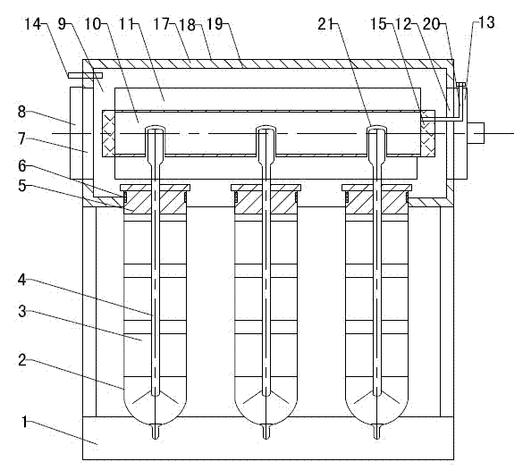
[0029] Refer to attached figure 1 : This kind of solar air heat collector comprises frame 1, vacuum glass heat collecting tube, metal heat pipe 4, sealing plug 5, sealing ring 6, air filter 8, air heat collecting chamber 9, finned radiator 10 and start Closing device 13. The air heat collecting chamber 9 is a rectangular shell, which is installed on the top of the vacuum glass heat collecting tube. The upper part of the vacuum glass heat collecting tube extends into the air heat collecting chamber 9. Upper and air heat collecting chamber 9 are provided with the installation hole that vacuum glass heat collecting tube is installed and are connected as a whole. The longitudinal section of the air heat collection chamber 9 can be circular, semicircular, elliptical, fan-shaped, rectangular or rhombus. The overall longitudinal section of the fin radiator 10 is circular, elliptical, semicircular, sectoral, trapezoidal, rhombus or rectangular.

[0030] The air heat collection cham...

Embodiment 2

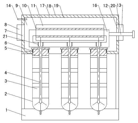
[0035] Refer to attached figure 2 : There are multiple vacuum glass heat collecting tubes, and multiple vacuum glass heat collecting tubes are installed side by side on the same side of the air heat collecting chamber 9, and the two ends of the fin radiator 10 or the sides of both ends are connected by elbow joints, tee pipes and other connecting parts Connected with the flow pipe 16, the condensing end of the top of the metal heat pipe 4 is inserted into the heat transfer sleeve 21 arranged side by side on the flow pipe 16, and a medium filling pipe 20 is extended on one side of the flow pipe 16, and the medium filling pipe 20 one end extends out of the air heat collection chamber 9 as a medium filling port, and is provided with a pressure relief device. The heat at the condensing end at the top of the plurality of metal heat pipes 4 is transferred to the fin radiator 10 in the air heat collection chamber 9 through the heat storage and heat conduction medium in the flow chan...

Embodiment 4

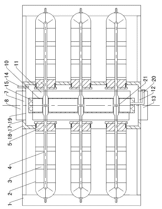
[0040] Refer to attached Figure 4 A plurality of vacuum glass heat collecting tubes are arranged side by side, and the plurality of vacuum glass heat collecting tubes are divided into two groups. There are two sections, which are symmetrically installed on both sides of the air heat collection chamber 9, respectively connected to the condensation ends of the metal heat pipes 4 at corresponding positions, and two sets of vacuum glass heat collection tubes are symmetrically installed in the air heat collection chamber 9 through two sections of flow channel pipes 16. Two sets of vacuum glass heat collecting tube bottoms are fixedly installed on the frame 1 and connected with the air heat collecting chamber 9 as a whole through the frame 1. A partition is respectively arranged between the two flow pipes 16 and the finned radiator 10, and the finned radiator 10 is installed in the space formed between the two partitions, and other settings and working process are the same as in th...


PUM


Abstract

The invention provides a solar vacuum glass heat collecting tube air heat collector, belongs to the field of solar air heating equipment, and particularly relates to a device which uses a solar vacuum glass heat collecting tube and a metal thermal tube which are combined for air heating and heat collecting. The solar vacuum glass heat collecting tube air heat collector is characterized in that a fan radiator (10) is arranged inside an air heat collecting chamber (9), the air heat collecting chamber (9) is connected with a condensing end at the top end of the metal thermal tube (4) through the fin radiator (10), and radiating fins (11) which are distributed in a radiating shape mode are arranged on the outer peripheral ring of the fin radiator (10). The solar vacuum glass heat collecting tube air heat collector has the advantages of being high in heat transmission speed, high in solar heat energy utilization ratio, good in sealing effect and the like.

Description

technical field [0001] A solar air heat collector belongs to the field of solar air heating equipment, and in particular relates to a device for air heating and heat collection by combining a solar vacuum glass heat collecting tube and a metal heat pipe. Background technique [0002] With the increasing shortage of coal, oil and other energy sources and the increasing pressure on environmental protection, countries have begun to promote renewable energy. Among them, the development and utilization of solar energy has become the hottest new favorite among renewable energy sources, and the development and utilization of solar energy has become an irresistible trend. . First of all, solar thermal has been developed in our country for many years, but most of them are concentrated in the field of solar hot water application. The technical development of solar hot air is relatively weak and has not been effectively utilized. However, the solar hot air system is not in terms of cos...

Claims


Application Information

Patent Timeline
Patent Type & Authority Patents(China)
IPC IPC(8): F24J2/32F24J2/05F24J2/46F24S10/40F24S10/95
CPCY02E10/44F24S10/45F24S10/75
Inventor 张勇
Owner 泰州市华驰不锈钢制品有限公司
Why Eureka
Try Eureka