Shield tunnel excavation surface stability centrifuge model test matching apparatus

A technology of centrifugal model testing and shield tunneling, applied in the direction of measuring devices, strength characteristics, instruments, etc., to achieve good scalability

Inactive Publication Date: 2013-06-26
TONGJI UNIV
View PDF3 Cites 25 Cited by
  • Summary
  • Abstract
  • Description
  • Claims
  • Application Information

AI Technical Summary

Problems solved by technology

Secondly, the soil is a three-phase medium, which is heterogeneously distributed in the natural state formation, but the soil can only be regarded as a homogeneous distribution in the numerical calculation process

Method used


Image

  • Shield tunnel excavation surface stability centrifuge model test matching apparatus
  • Shield tunnel excavation surface stability centrifuge model test matching apparatus
  • Shield tunnel excavation surface stability centrifuge model test matching apparatus

Examples


Embodiment 1

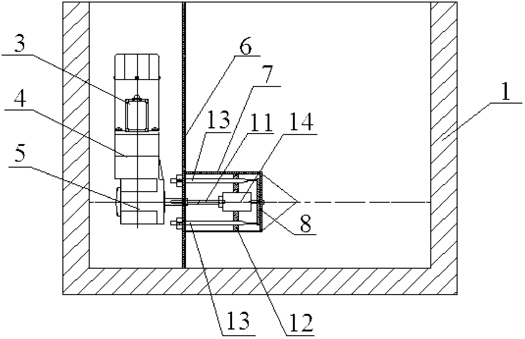
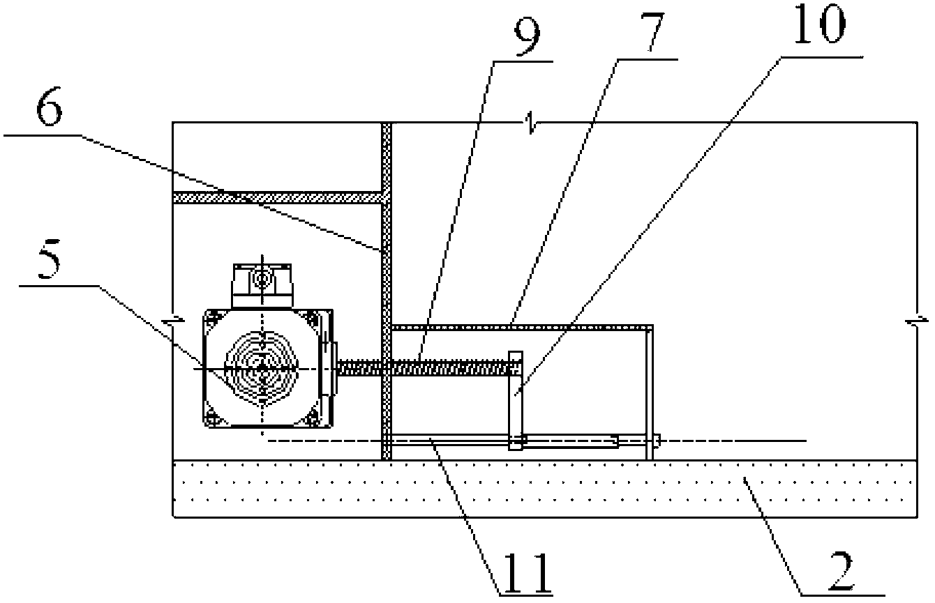
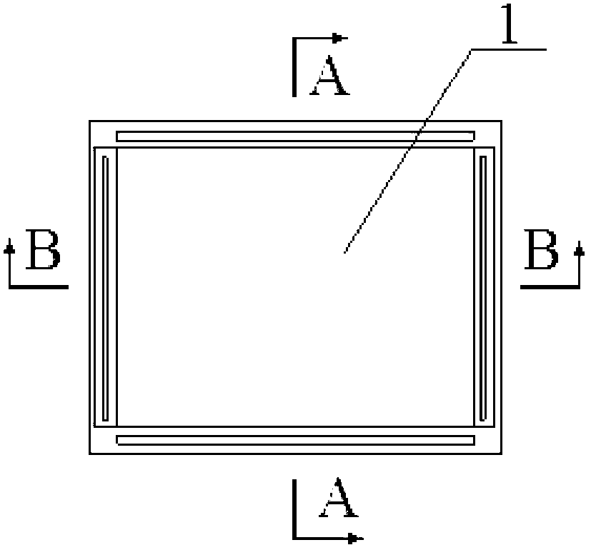
[0040] A supporting device for the centrifugal model test of the excavation face stability of a shield tunnel, such as Figure 1 to Figure 5As shown, the model box 1 is included, the front side of the model box 1 is a plexiglass window 2, the upper side of the model box 1 is provided with an opening, the model box 1 is located in the centrifugal testing machine, and the model box 1 is provided with a model tunnel 7, Tunnel rigid support surface 8, power components, transmission components and data acquisition components. Among them, the model tunnel 7 is located in the model box 1, and the outside of the model tunnel 7 is filled with test foundation soil; the rigid support surface 8 of the tunnel is set on the top of the inside of the model tunnel 7; the power component is set on the outside of the model tunnel 7, and the power component includes The connected three-phase asynchronous motor 3, continuously variable transmission 4 and worm gear reducer 5; the transmission assem...

Embodiment 2

[0052] The inner diameter of a large-diameter shield tunnel is 15m, the buried depth ratio is about 1, and the foundation soil is divided into sandy soil layers. It is necessary to conduct centrifugal model test research on the process of soil instability and destruction due to insufficient support pressure on the shield excavation face, and obtain relevant data.

[0053] For such problems, follow the Figure 1 ~ Figure 2 Satisfactory results can be achieved by adjusting the output speed of the displacement control system and determining the parameters of the foundation soil according to the actual situation of the project and geological conditions.

[0054] The test uses Tongji University TLJ-150 composite rock and soil centrifugal testing machine, and the internal size of the model box 1 is 900mm×700mm×700mm (length×width×height). The centrifugal acceleration is 100g during the official test. Therefore, the inner diameter of the model tunnel 7 is 150 mm. The earth pressur...


PUM


Abstract

The invention relates to a shield tunnel excavation surface stability centrifuge model test matching apparatus. The apparatus comprises a model case, and a model tunnel, a rigid tunnel support surface, a power assembly, a transmission assembly and a data acquisition assembly are arranged in the model case, wherein the model tunnel is positioned in the model case, and the outside of the model tunnel is filled with test foundation soil; the rigid tunnel support surface is arranged at the top in the model tunnel; the power assembly is arranged at the outside of the model tunnel; the transmission assembly is arranged in the model tunnel and is connected with the power assembly and the rigid tunnel support surface; the data acquisition assembly comprises a force transducer, an LVDT displacement meter and a soil pressure gauge; the power assembly provides power for the rigid tunnel support surface through the transmission assembly, and drives the rigid tunnel support surface to move to control the displacement of the rigid tunnel support surface and stimulate the instability process of tunnel excavation surface soil, and the data acquisition assembly synchronously acquires data. Compared with apparatuses in the prior art, the apparatus provided by the invention has the advantages of simple structure, use convenience, stable and sensitive running, and wide application range.

Description

technical field [0001] The invention belongs to the field of tunnel engineering of geotechnical and underground engineering, and in particular relates to a supporting device for a centrifugal model test of the excavation surface stability of a shield tunnel. Background technique [0002] In the process of tunnel excavation, applying reasonable support pressure to the excavation face is the key to ensure construction safety. Excessive support pressure on the excavation surface will cause collapse and damage to the excavation surface, while excessive support pressure will cause ground uplift. The current research on support pressure mainly includes theoretical, numerical and experimental methods. Nowadays, the numerical simulation method is widely used because of its simplicity, quickness and low cost. Based on some assumptions, it can be used to analyze the damage of the excavation surface caused by insufficient or excessive support pressure during the excavation of the shi...

Claims


Application Information

Patent Timeline
Patent Type & Authority Applications(China)
IPC IPC(8): G01N3/00
Inventor 吕玺琳黄茂松李冯缔
Owner TONGJI UNIV
Why Eureka
Try Eureka