Supercharge Your Innovation With Domain-Expert AI Agents!

CTP (Computer to Plate) plate surface detection method and system based on machine vision

A technology of machine vision and surface inspection, which is applied in the direction of optical testing for flaws/defects, can solve problems such as large economic losses, high labor costs, and increased production line speed, so as to reduce economic losses, reduce labor costs, and reduce missed inspections. Effect

Active Publication Date: 2013-06-26
BEIJING C&W ELECTRONICS GRP +1
View PDF6 Cites 4 Cited by
  • Summary
  • Abstract
  • Description
  • Claims
  • Application Information

AI Technical Summary

Problems solved by technology

[0005] 1. High missed detection rate: due to the subjective factors of limited people, the probability of missed detection during the CTP version detection process is very high;
[0006] 2. High cost: the missed detection rate is high, and the manufacturer will suffer a large economic loss; moreover, with the increase of workers' wages, the labor cost of the manufacturer will also become higher and higher;
[0007] 3. Low detection accuracy: relying solely on manual detection, the detection accuracy is bound to be very low;
[0008] 4. Low production efficiency: manual inspection restricts the speed of the production line; and the production environment of the CTP version is slightly toxic, and long-term inspection will affect the detection efficiency and affect the health of workers;

Method used


Image

  • CTP (Computer to Plate) plate surface detection method and system based on machine vision
  • CTP (Computer to Plate) plate surface detection method and system based on machine vision
  • CTP (Computer to Plate) plate surface detection method and system based on machine vision

Examples


Embodiment Construction

[0043] The specific implementation manners of the present invention will be further described in detail below in conjunction with the accompanying drawings and embodiments. The following examples serve to illustrate the present invention, but do not limit the scope of the present invention.

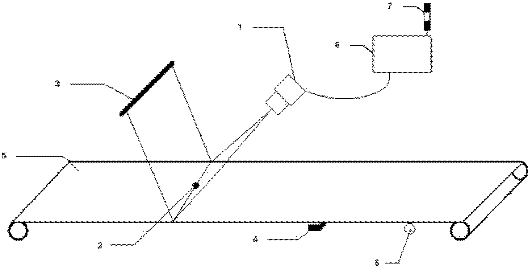
[0044] The CTP plate surface detection system based on machine vision of the present invention includes image acquisition equipment, image processing equipment, system lighting equipment and warning lights; wherein, the image acquisition equipment is used to collect the original image information of the CTP plate surface; The image processing device is used to process the original image information collected by the image acquisition device; the system lighting device is used to provide imaging lighting for the image acquisition device; When the processing results indicate that there are defects on the surface of the CTP plate, an alarm will be given.

[0045] Such as figure 1 Shown, one...


PUM

PropertyMeasurementUnit
Light wavelengthaaaaaaaaaa

Abstract

The invention provides a CTP (Computer to Plate) plate surface detection method based on machine vision and a CTP plate surface detection system based on the machine vision. The system comprises image acquiring equipment, image processing equipment, system lighting equipment and an alarm light, wherein the image acquiring equipment is used for acquiring the information of the original image of the surface of a CTP plate; the image processing equipment is used for processing the original image information acquired by the image acquiring equipment; the system lighting equipment is used for providing imaging light to the image acquiring equipment; and the alarm light is used for warming for reminding once the processing result of the image processing equipment shows defects occurring on the surface of the CTP plate. The CTP plate surface detection system is used in match with the conventional CTP plate production line to realize the real-time online detection of the surface of the CTP plate, and reduces the omission factor, releases the manual labor, decreases the production cost of manufacturers, improves the detection precision, as well as improves the industrial automation level of a production line.

Description

technical field [0001] The invention relates to the fields of machine vision detection and industrial automation, in particular to a machine vision-based CTP plate surface detection method and system. Background technique [0002] CTP (Computer-to-plate) is an abbreviation for computer-to-plate, and it is a high-quality printing plate for lithographic printing. Since its inception, it has developed rapidly around the world and is now widely used in the printing of newspapers, magazines, and books. During the production process, due to the quality of raw materials, production process and other reasons, the surface of the CTP plate will have blemishes or defects, such as decoating, stains, scratches, wrinkles, etc., which will affect the quality of the product. [0003] At present, the domestic CTP plate manufacturers mainly rely on the naked eye recognition of workers for the detection of CTP plate surface defects. However, due to the subjective factors of limited people, t...

Claims


Application Information

Patent Timeline
IPC IPC(8): G01N21/88
Inventor 张富明徐江伟任婕王新新韩琦张广秀
Owner BEIJING C&W ELECTRONICS GRP
Features
  • R&D
  • Intellectual Property
  • Life Sciences
  • Materials
  • Tech Scout
  • Unparalleled Data Quality
  • Higher Quality Content
  • 60% Fewer Hallucinations
Learn More