Plane interaction system and method based on binocular vision recognition

A technology of binocular visual recognition and interactive system, applied in the field of plane touch control system, can solve the problems of high-speed real-time spatial coordinate tracking of difficult targets, target recognition errors, errors prone to binocular visual recognition, etc., and achieves high installation flexibility, Cost reduction and portability

Active Publication Date: 2013-06-26
SHANGHAI TUYANG INFORMATION TECH CO LTD
View PDF5 Cites 10 Cited by
  • Summary
  • Abstract
  • Description
  • Claims
  • Application Information

AI Technical Summary

Problems solved by technology

However, when the target is placed in a more complex background, target recognition errors may occur. For example, if a target with stripes on the surface is placed in front of a striped background, binocular vision recognition is prone to errors. Therefore, line-type laser assistance is often used at present. Scanning to exclude interference from complex backgrounds
In addition, because the binocular vision system needs to process a large amount of image information, it is difficult to track the target in high-speed real-time space coordinates

Method used


Image

  • Plane interaction system and method based on binocular vision recognition
  • Plane interaction system and method based on binocular vision recognition
  • Plane interaction system and method based on binocular vision recognition

Examples


Embodiment Construction

[0018] Embodiments of the present invention will be described below with reference to the accompanying drawings.

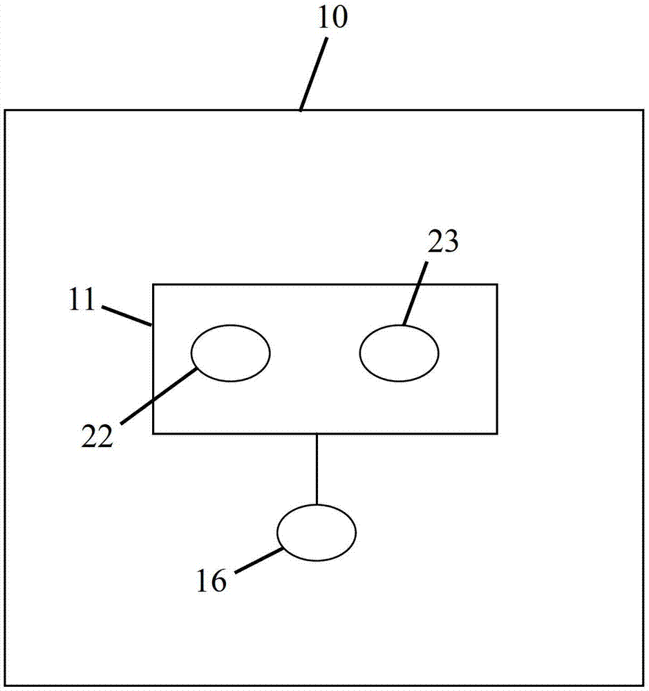
[0019] Figure 1A is a schematic diagram of a plane interaction system 10 based on binocular visual recognition according to an embodiment of the present invention.

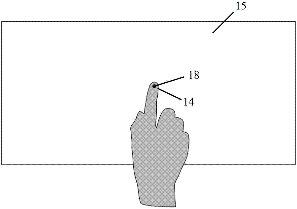
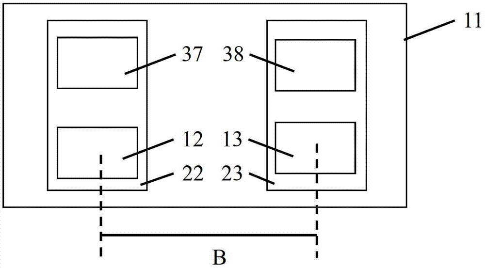
[0020] System 10 includes imaging device 11 and processor 16 . The imaging device 11 includes two imaging assemblies 22 and 23, and the imaging assemblies 22 and 23 are respectively for such as Figure 1B The objects 14 on the interaction plane 15 are shown simultaneously with successive image captures. The interaction plane 15 is defined by three points that are not collinear in space. The design requirements of the imaging device 11 will be referred to below figure 2 to describe.

[0021] The processor 16 processes the image information from the imaging device 11 , performs matching calculation on the images from the imaging components 22 and 23 at the same time, and derives an interactive res...


PUM


Abstract

The application relates to a plane interaction system and method based on binocular vision recognition. The plane interaction system comprises an imager and a processor, wherein the imager comprises two imaging components which are distributed by a relatively fixed space relationship, and the two imaging components are used for capturing images of targets at the same time; and the processor is configured to process image parallax errors of feature points of the targets captured at the same time, computing space coordinates of the feature points, confirming the space relationship between the feature points and a set interaction plane according to the space coordinates of the feature points, and outputting the interaction response.

Description

technical field [0001] The present invention relates to a plane touch control system, and more particularly, to a plane interaction system and method based on binocular visual recognition. Background technique [0002] The flat touch control system is a computer input method. Different from the traditional mouse and keyboard input methods, the planar touch control system calculates the coordinates of the touch points and inputs them to the computer to achieve the purpose of directly operating the virtual objects in the computer. At present, many known technologies have been applied to the planar touch control system. [0003] Resistive touch screen technology uses pressure sensing for control, and is a touch technology widely used on touch terminals. The working principle is that on a transparent substrate coated with a metal oxide conductive layer on the upper surface, a layer of transparent plastic plate coated with a metal oxide conductive layer on the lower surface is ...

Claims


Application Information

Patent Timeline
Patent Type & Authority Applications(China)
IPC IPC(8): G06F3/01
Inventor 王敏捷梁雨时史保华
Owner SHANGHAI TUYANG INFORMATION TECH CO LTD
Why Eureka
Try Eureka