Antenna unit

An antenna unit and antenna technology, which is applied to antennas, slot antennas, antenna arrays, etc., can solve the problems of inability to adjust the vertical and horizontal beams, low energy utilization, etc., to improve antenna efficiency, high gain, and improve flexibility Effect

Active Publication Date: 2013-06-26
JIANGSU EAST CENTURY NETWORK INFORMATION +1
View PDF5 Cites 1 Cited by
  • Summary
  • Abstract
  • Description
  • Claims
  • Application Information

AI Technical Summary

Problems solved by technology

U.S. Patent US6259416B1 discloses an antenna combined with a slot ring structure. The antenna has relatively high gain and relatively wide frequency band characteristics. However, the antenna cannot effectively and freely control the longitudinal radiation and the transverse beam cannot be adjusted. , the energy utilization rate is low, for example, it cannot meet the requirements of modern communication technology for antennas, such as LTE antennas

Method used


Image

  • Antenna unit
  • Antenna unit
  • Antenna unit

Examples


Embodiment 1

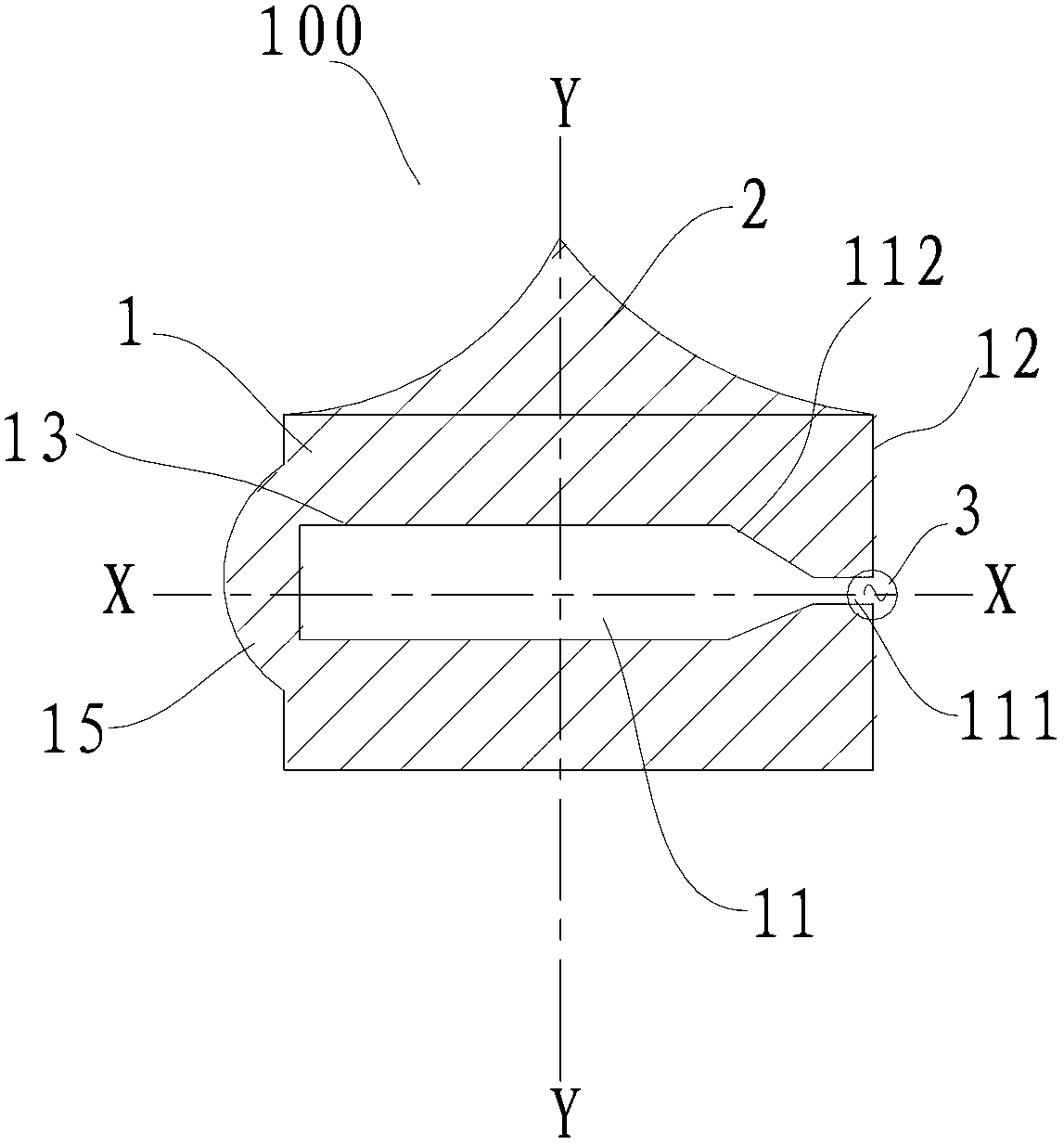
[0075] Such as figure 1 As shown, the antenna unit 100 in this embodiment includes: a first antenna component 1, a second antenna component 2 and a feed component 3, the ring structure of the first antenna component 1 has a slot 11 formed in a rectangular shape , and there is a tapered transition section 112 between the slot 11 and the opening 111 .

[0076] The second antenna component 2 is formed in a triangular shape, specifically, the long side of the second antenna component 2 is parallel to and adjacent to the first antenna component 1 , while the other two sides are formed as arc segments and intersect at a tip.

Embodiment 2

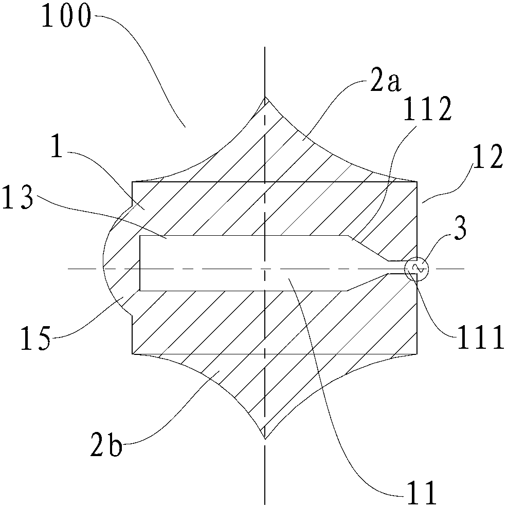
[0078] Such as figure 2 As shown, the structure of the antenna unit 100 according to this embodiment is substantially the same as that of the antenna unit 100 in Embodiment 1, the only difference is that the antenna unit 100 in this embodiment includes two second antenna components 2 . One 2a of the two second antenna elements 2 is connected to the first side of the first antenna element 1 (as Figure 2-Figure 6 The upper side of the middle) is coupled by direct connection, and the other 2b of the two second antenna components 2 is connected to the second side of the first antenna component 1 opposite to the first side (such as Figure 2-Figure 6 in the lower side) are coupled by direct connection.

Embodiment 3

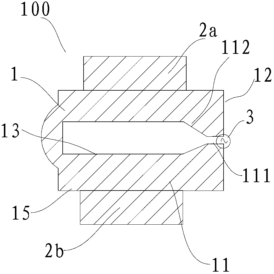
[0080] Such as image 3 As shown, the structure of the antenna unit 100 according to the present embodiment is substantially the same as that of the antenna unit 100 in the second embodiment, the only difference is that the two second antenna components 2 of the antenna unit 100 in the present embodiment are both formed as Rectangular shape, in this case, the long side of the rectangle formed in the second antenna element 2 is parallel to and adjacent to the first (or second) side of the first antenna element 1 .


PUM


Abstract

The invention discloses an antenna unit comprising a first antenna component, a second antennal component and a feeding pack. The first antenna component is provided with an annular structure with a groove, and the annular structure is provided with an outer periphery and an inner periphery outlined by the groove. The second antenna component and the first antenna component are coupled together. The feeding pack and the first antenna component are coupled together to feed the first antenna component. According to an embodiment of the antenna unit, the second antenna component is arranged to control vertical radiation of an antenna and reduce the radiation of other directions, so that effective energy can be concentrated on the right directions, beam control is realized, and antenna efficiency is improved.

Description

technical field [0001] The invention relates to the technical field of communications, in particular to an antenna unit. Background technique [0002] With the development of modern LTE, 3G and other communication technologies, the requirements for antenna performance are getting higher and higher, such as requiring broadband, which can cover the working frequencies of 2G, 3G and 4G at the same time, and has high gain. The radiation direction of the antenna Maps also need to be effectively controlled. U.S. Patent US6259416B1 discloses an antenna combined with a slot ring structure. The antenna has relatively high gain and relatively wide frequency band characteristics. However, the antenna cannot effectively and freely control the longitudinal radiation and the transverse beam cannot be adjusted. , the energy utilization rate is low, for example, it cannot meet the requirements of modern communication technologies for antennas, such as LTE antennas. Contents of the invent...

Claims


Application Information

Patent Timeline
Patent Type & Authority Applications(China)
IPC IPC(8): H01Q1/36H01Q5/00H01Q13/10H01Q21/00
Inventor 漆一宏于伟
Owner JIANGSU EAST CENTURY NETWORK INFORMATION
Why Eureka
Try Eureka