
Transmission line self-adaptive single-end transient protection based on transition resistance and fault angle reductions

A transition resistance and transient protection technology, applied in the direction of emergency protection circuit devices, electrical components, etc., can solve the problems of unreliable and unstable performance of single-ended transient protection, and achieve high reliability of protection action, easy setting, and improved The effect of protecting reliability

Active Publication Date: 2013-06-26
郭振威
View PDF4 Cites 13 Cited by
  • Summary
  • Abstract
  • Description
  • Claims
  • Application Information

AI Technical Summary

Problems solved by technology

[0003] Therefore, aiming at the shortcomings and deficiencies of traditional single-ended transient protection that are not reliable enough and not stable enough, the patent of the present invention breaks through the limitations of traditional transient protection on the basis of in-depth analysis of the transient process mechanism, and proposes a A new type of single-ended transient protection method based on transient quantities calculated according to transition resistance and fault angle. This protection method has high reliability, self-adaptive fault type and the ability of transition resistance and fault angle, stable performance and ultra-high speed performance

Method used


Image

  • Transmission line self-adaptive single-end transient protection based on transition resistance and fault angle reductions

Examples


Embodiment

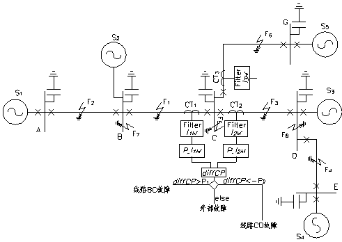
[0017] figure 1 Shown is a 500kV EHV transmission line model. In this model, AB The section line length is 180km, BC The section line length is 342km, cd The section line length is 360km, DE The line length of this section is 266km, CG The section line length is 270km. S 1 =35MVA,S 2 =10MVA, S 3 =20MVA,S 4 =5MVA,S 5 =12MVA. Line parameters X 1 , R 1 , C 1 , X 0 , R 0 , C 0 respectively X 1 =0.2783Ω / km, R 1 =0.0270Ω / km, X 0 =0.6494Ω / km, R 0 =0.1948Ω / km, C 1 =0.0127μF / km, C 0 =0.0090μF / km. The capacitance of each busbar to ground is 6000PF. right figure 1 In the shown ultra-high voltage transmission line, the adaptive single-ended transient protection of the transmission line is calculated based on the transition resistance and the fault angle, including the following steps.

[0018] Step 1: Collect busbars C Transient current on both sides I 1 , I 2 , to extract the transient current I 1 and I 2 high frequency components I ...


PUM


Abstract

The invention discloses transmission line self-adaptive single-end transient protection based on transition resistance and fault angle reductions. When the transmission line is in short circuit, a large amount of high-frequency signals produced by a fault are transmitted to two ends of the transmission line; and owing to affect of earth distributed capacitance of a bus, the high-frequency signals are obviously reduced via the bus, high-frequency component close to the fault side of the bus is invariably higher than that of the fault side of the bus, and the transition resistances and fault angles have a great affect on the high-frequency component produced by the fault. Relative reduction formulas and parameters are selected according to the type of the fault, the transient amount reduction is performed corresponding to the transition resistances and the fault angles, and protective criterion is constructed according to the reduction transient amount. According to the principle, fault feature amount with both directional elements and number comparing functions are constructed on the basis of the transient amount difference of reduction of two sides of the bus to determine a zone the fault occurs in. By the aid of the scheme, the affect to the single-end transient protection by the transition resistances and fault angle is eliminated to a maximum extent. Fault feature differences between the forward direction and reverse direction and inner zone and external zone are obvious, reliability and flexibility are high, the overall length of a line can be protected, protecting areas are twice that of traditional protecting areas, and requirements for the distributed capacitance of the bus are low.

Description

technical field [0001] The invention relates to the protection technology of electric power transmission lines, in particular to a method for protecting transmission lines by using single-ended transient quantities calculated according to transition resistance and fault angle to realize the identification of faults inside and outside the area of ​​the line. Background technique [0002] The single-ended transient protection constructed by using the single-ended transient high-frequency components of transmission line faults can maximize the protection action speed, and is not affected by the saturation of current transformers and power frequency short-circuit levels. It also has the advantages of saving communication channel construction costs, Reliability is not affected by the normal operation of the communication channel and peer protection. Therefore, single-ended transient protection has been widely concerned and continuously studied by domestic scholars and researchers ...

Claims


Application Information

Patent Timeline
Patent Type & Authority Applications(China)
IPC IPC(8): H02H7/26
Inventor 郭振威姚建刚
Owner 郭振威
Learn More