
Main lobe interference suppression method and device

A technology of main lobe interference and optimal weight vector, applied in the field of communication, can solve the problems of increased side lobe level, decreased output signal-to-noise ratio, offset, etc., and achieves the effect of improving main beam pointing and improving suppression performance.

Active Publication Date: 2017-08-25
ZTE CORP
View PDF3 Cites 0 Cited by
  • Summary
  • Abstract
  • Description
  • Claims
  • Application Information

AI Technical Summary

Problems solved by technology

[0004] The present invention provides a main lobe interference suppression method and device to at least solve the problem in the related art that the application of conventional adaptive beamforming technology to suppress main lobe interference will lead to increased side lobe level, main beam deformation and peak shift, resulting in The problem of output signal-to-noise ratio drop

Method used


Image

  • Main lobe interference suppression method and device
  • Main lobe interference suppression method and device
  • Main lobe interference suppression method and device

Examples


Embodiment Construction

[0023] It should be noted that, in the case of no conflict, the embodiments in the present application and the features in the embodiments can be combined with each other. The present invention will be described in detail below with reference to the accompanying drawings and examples.

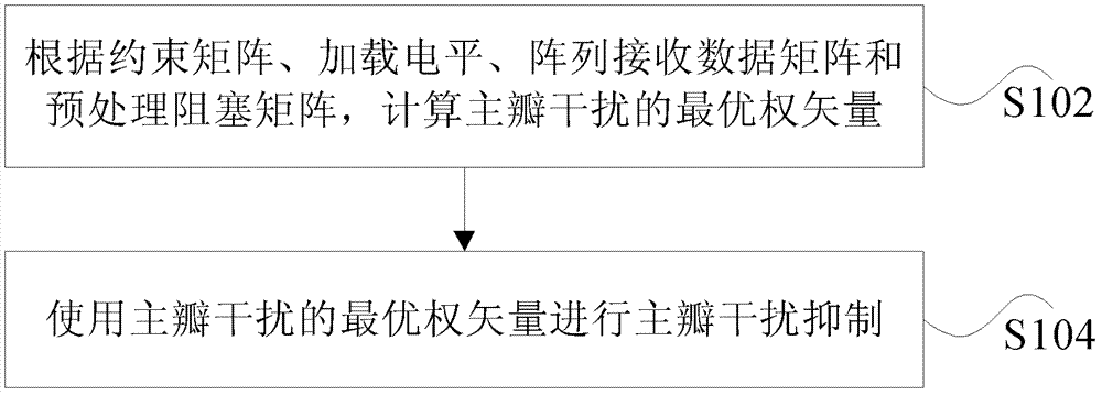
[0024] The invention provides a main lobe interference suppression method, figure 1 is a flow chart of a main lobe interference suppression method according to an embodiment of the present invention, such as figure 1 As shown, the following steps S102 to S104 are included.

[0025] Step S102, calculating the optimal weight vector of the main lobe interference according to the constraint matrix, the loading level, the array receiving data matrix and the preprocessing blocking matrix.

[0026] Step S104, using the optimal weight vector of the main lobe interference to suppress the main lobe interference.

[0027] In related technologies, the application of conventional adaptive beamforming tec...


PUM


Abstract

The invention discloses a main lobe interference suppression method and device. The method includes calculating an optimal weight vector of main lobe interference according to a constraint matrix, a load electrical level, an array receive data matrix and a preprocessing block matrix; and using the optimal weight vector of main lobe interference to perform main lobe interference suppression. By means of the main lobe interference suppression method and device, main beams are enabled to point to an expected target direction, and simultaneously, main lobe interference is inhibited from forming deep null steering in other interference directions.

Description

technical field [0001] The present invention relates to the communication field, in particular to a main lobe interference suppression method and device. Background technique [0002] With the development of mobile communication, smart antenna technology is also applied in mobile communication of multi-antenna system. The smart antenna uses digital signal processing technology to generate spatially directional beams, so that the main beam of the antenna is aligned with the direction of the desired user signal, and the side lobes or nulls are aligned with the direction of the interference signal, so as to effectively receive the desired mobile user signal and suppress or eliminate the useless interference signal. . [0003] In the presence of mainlobe interference, applying conventional adaptive beamforming techniques will result in increased sidelobe levels, distortion of the main beam, and shifted peaks, thereby degrading the output SNR. When the main lobe interference is...

Claims


Application Information

Patent Timeline
Patent Type & Authority Patents(China)
IPC IPC(8): H04B7/06
Inventor 曾召华李斌史凡秦洪峰刘聪锋甘昶冯汝鹏
Owner ZTE CORP
Learn More