Chip welding method of dual-interface card and equipment thereof

A chip welding and dual-interface card technology, which is applied in welding equipment, metal processing equipment, manufacturing tools, etc., can solve the problems of dual-interface cards that take a long time, affect the chip, and false soldering, and avoid collisions or vibrations. And false welding, reduce empty travel or inaccurate positioning, the effect of broad application prospects

Inactive Publication Date: 2013-07-03
GUANGZHOU MINGSEN TECH CO LTD
View PDF6 Cites 15 Cited by
  • Summary
  • Abstract
  • Description
  • Claims
  • Application Information

AI Technical Summary

Problems solved by technology

[0003] The current mainstream process for the production of dual-interface cards is to use pick-and-butt welding. The process mainly includes the following steps: the first step is to make the card body with the built-in antenna by lamination, and the second step is to make the card body with the built-in antenna The third step is to solder the antenna and the chip, and then package it. The third step is: manually position the two ends of the lifted antenna and solder them to the chip one by one. The strength is high, the work efficiency is low, and the gas generated during welding has a negative impact on the health of the operator. Therefore, people began to develop an automatic welding technology, but it can only weld one end of the antenna at the same time. , so the welding of a dual-interface card requires two welding processes. The long time spent on a dual-interface card leads to low work efficiency, and when the two ends of the antenna are welded separately, when one end of the antenna is welded, production collisions Or vibration, which affects the position of the positioned chip, so that false welding may occur when soldering the other end of the antenna, affecting product quality and service life, and cannot meet production requirements

Method used


Image

  • Chip welding method of dual-interface card and equipment thereof
  • Chip welding method of dual-interface card and equipment thereof
  • Chip welding method of dual-interface card and equipment thereof

Examples


Embodiment 1

[0056] The following is a preferred specific implementation example of the present invention, a chip welding method for a dual-interface card, comprising the following steps:

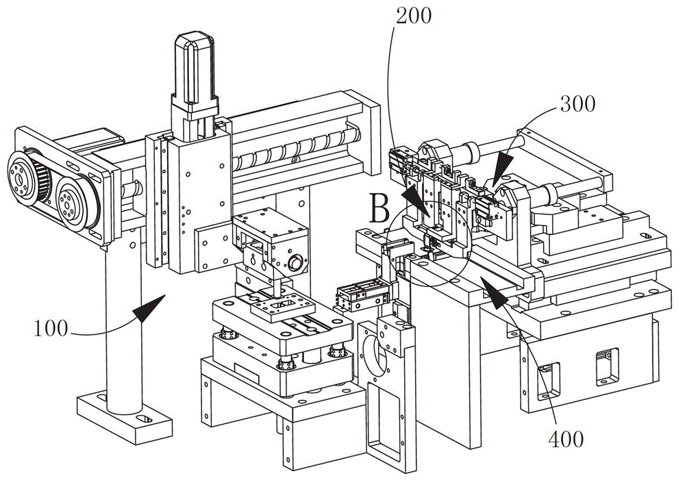
[0057] Step 1, the card body reaches the position to be welded through the card body conveying device, and the two ends of the antenna of the card body are in the erected state; the chip pick-up device picks up the chip and arrives at the position to be welded;

[0058] Step 2, the clamping device simultaneously clamps both ends of the antenna and locates it at the welding position of the chip;

[0059] Step 3, the two ends of the positioned antenna are welded to the chip by the double-touch welding head;

[0060] Step 4, after the welding is completed, the double-touch welding head returns to its position, and then the clamping device loosens the clamping and positioning of the two ends of the antenna, and then the card body conveying device transports away the welded card body.

[0061] The second st...

Embodiment 2

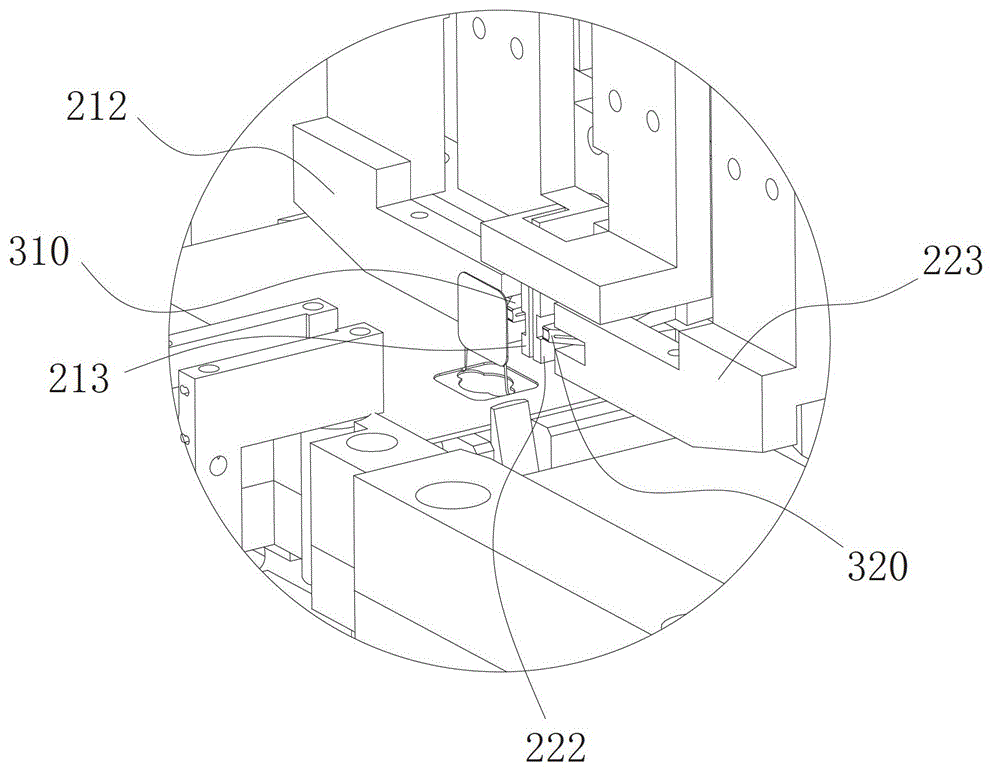
[0077] Such as Figure 18-26As shown, the difference between this preferred specific implementation example and Embodiment 1 lies in that: the two gripping fingers of the first grasping and positioning hand 210A are specifically the first gripping finger 212A and the second gripping finger 222A, and the second gripping The two clamp fingers of the positioning hand 220A are specifically the third clamp finger 213A and the fourth clamp finger 223A, and the first clamp finger 212A, the second clamp finger 222A, the third clamp finger 213A and the fourth clamp finger 223A are sequentially slidably connected to the On the backing plate 240, a spring is connected between the first clamping finger 212A and the fourth clamping finger 223A, and a spring is connected between the second clamping finger 222A and the third clamping finger 213A. The positioning hand driver 230 includes a slider 231A and a slider pneumatic part 232A installed between the first grasping and positioning hand 2...


PUM

PropertyMeasurementUnit
thicknessaaaaaaaaaa

Abstract

The invention discloses a chip welding method of a dual-interface card. The chip welding method of the dual-interface card comprises the following steps: 1, a card body is conveyed by a card body conveying device to a position on which the chip is to be welded, wherein the two ends of an antenna of the card body are at an erect state; and a chip pickup device picks up a chip and reaches the position on which the chip is to be welded to be welded; 2, an antenna clamping device clamps the two ends of the antenna at the same time and positions the antenna at the welded position of the chip; 3, a dual-touch welding head welds the two ends of the positioned antenna on the chip; and 4, after welding, all components return and the card body conveying device takes away the welded card body. The invention further discloses chip welding equipment of the dual-interface card for implementing the chip welding method of the dual-interface card. The chip welding equipment of the dual-interface card comprises the chip pickup device, the antenna clamping device, the card body conveying device and the dual-touch welding head, wherein the chip pickup device is arranged on one side of the antenna clamping device; and the dual-touch welding head is arranged on the other side of the antenna clamping device. By the chip welding method and the chip welding equipment, the two ends of the antenna can be welded on the chip by one step.

Description

technical field [0001] The invention relates to a production method and equipment of a dual-interface card, more specifically, a chip welding method and equipment for a dual-interface card. Background technique [0002] The dual-interface card is a smart card based on a single chip that integrates contact and non-contact interfaces. RF way to access the chip. The card body of the dual-interface card is provided with an antenna and a chip, wherein the antenna is clamped in the card body, the chip is embedded in the card body and the contacts are exposed, and the two ends of the antenna are connected to the chip; through the antenna and the card reader The induction realizes the non-contact card reading, and the contact card reading is realized through the contacts of the chip contacting the card reader. [0003] The current mainstream process for the production of dual-interface cards is to use pick-and-butt welding. The process mainly includes the following steps: the firs...

Claims


Application Information

Patent Timeline
Patent Type & Authority Applications(China)
IPC IPC(8): B23K1/00
Inventor 王开来
Owner GUANGZHOU MINGSEN TECH CO LTD
Why Eureka
Try Eureka