Manufacturing method of plastic lens

一种塑料透镜、制造方法的技术,应用在其他家里用具、光学元件、家里用具等方向,达到防止熔接痕的产生的效果

Active Publication Date: 2017-09-05
HOYA CORP
View PDF2 Cites 0 Cited by
  • Summary
  • Abstract
  • Description
  • Claims
  • Application Information

AI Technical Summary

Problems solved by technology

Therefore, there is a tendency that a line called a "weld line" tends to be generated when the resin flowing in the cavity spreads and merges at the edge of the lens at the edge of the lens opposite to the gate. like traces
When such a weld line occurs, the defect in appearance or the reduction in strength due to the weld line will adversely affect the quality of the molded plastic lens.

Method used


Image

  • Manufacturing method of plastic lens
  • Manufacturing method of plastic lens
  • Manufacturing method of plastic lens

Examples


no. 1 approach

[0047] First, the first embodiment of the present invention will be described. The shape of the plastic lens to be molded in this embodiment is not particularly limited. The present invention can also be applied to a method of forming a semi-finished lens in a semi-finished state thicker than the finished size in advance, and finishing the semi-finished product called a "semi-finished lens" into a final shape by post-processing.

[0048] 【Injection molding equipment】

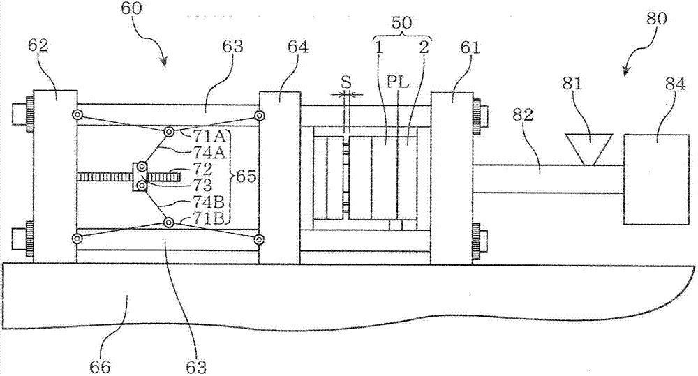
[0049] figure 1 It is an explanatory drawing which shows an example of the injection molding facility, and the manufacturing method of the plastic lens which concerns on this embodiment can be implemented suitably using such an injection molding facility.

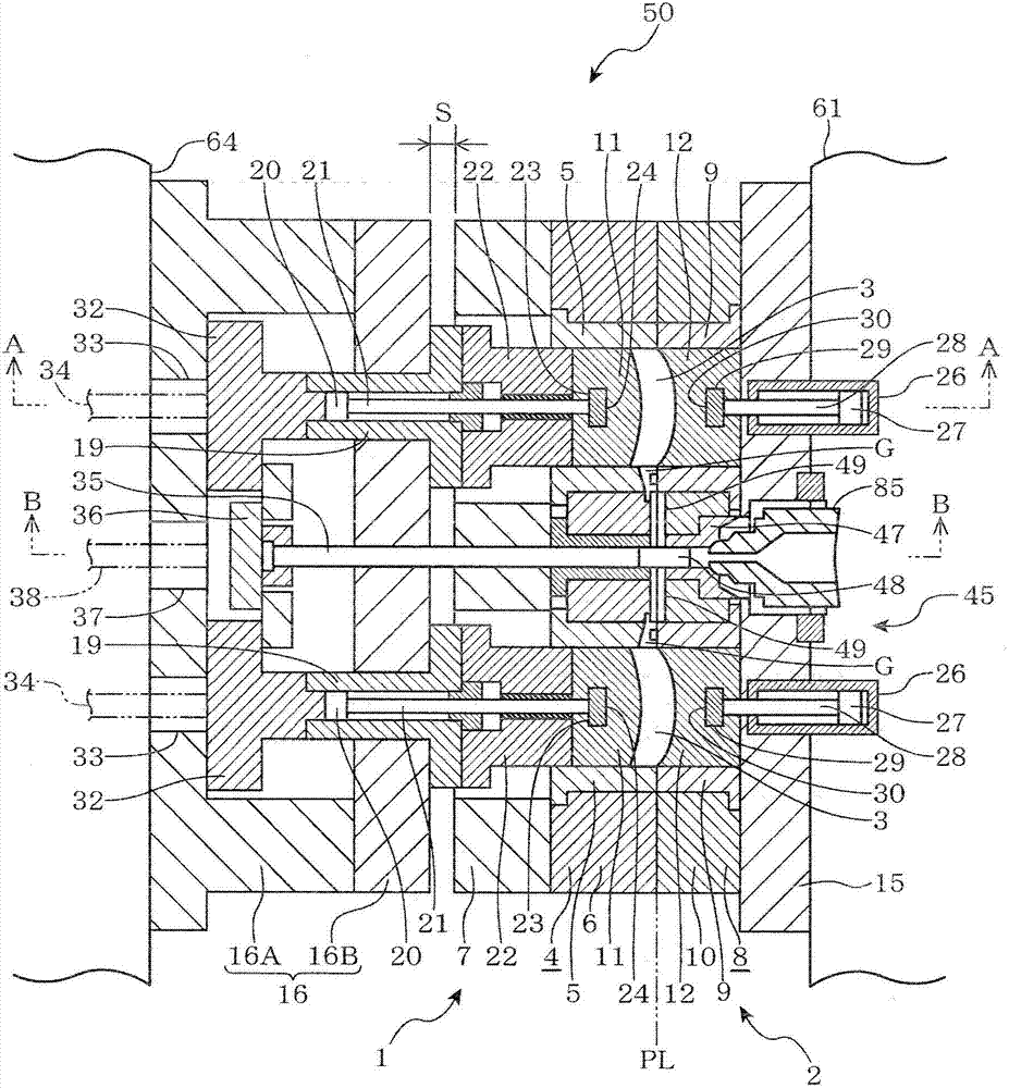
[0050] figure 1The injection molding apparatus shown is provided with a molding die 50, a clamping device 60, and an injection device 80, wherein the molding die 50 has a movable die 1 and a fixed die 2 that utilize a parting surface. (parting line) A pai...

no. 2 approach

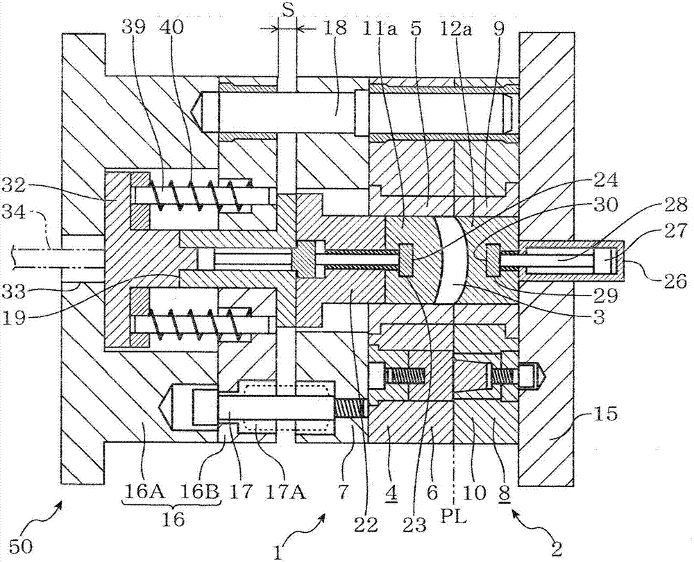
[0105] Next, a second embodiment of the present invention will be described. In the present embodiment, a negative lens (concave lens) having a thin thickness at the center of the lens and a thick thickness at the edge of the lens is used as a molding object. Suitable for the injection molding apparatus implemented in this embodiment, except that the cavity 3 of the molding die 50 formed between the movable die 1 and the fixed die 2 is formed corresponding to the shape of the negative lens, the other components are suitable for the first injection molding machine. The injection molding apparatus implemented by the embodiment is the same. Thus, in Figure 7 to Figure 10 In the figure, a cross-section of the molding die 50 having the cavity 3 formed in accordance with the shape of the negative lens is shown, and the same reference numerals are assigned to the common components, and the repeated description of the injection molding equipment is omitted.

[0106] in addition, ...

Embodiment 1

[0118] exist figure 1 In the injection molding equipment shown, the molding surface of the insert 11 on the side of the movable mold 1 and the side of the fixed mold 2 are respectively formed using insulating materials 11a and 12a composed of crown glass raw materials and having a thermal conductivity of 1.1W / m·K. The forming surface of the insert 12.

[0119] Using this injection molding equipment, polycarbonate is used as the raw material resin and the resin temperature is set to 290°C. At the same time, the setting of the mold temperature is changed to 125°C, 115°C, 85°C, 75°C, and 55°C. , 35° C., and a plastic lens having a thickness of 10 mm at the center of the lens, a thickness of 12.5 mm at the edge of the lens, and a diameter of 77 mm was formed.

[0120] As a result of checking the surface of the molded plastic lens, no surface defects were observed when the mold temperature was set at 125°C, 115°C, 85°C, 75°C, and 55°C, and when the mold temperature was lowered to ...


PUM

PropertyMeasurementUnit
thermal conductivityaaaaaaaaaa

Abstract

The manufacturing method of the plastic lens provided by the present invention does not heat the metal mold and the like, but can only maintain the resin injected and filled in the inner cavity at a temperature lower than its glass transition temperature during the period before the filling of the resin into the inner cavity is completed. Higher temperature, which can prevent the generation of surface defects such as injection marks or wave marks or weld lines; when injecting and filling the molten raw material resin to form between the movable mold (1) and the fixed mold (2) When manufacturing a plastic lens with a predetermined lens shape in the inner cavity (3) of the inner cavity (3), a part or the entire surface of at least one of the molding surfaces of the inserts (11, 12) as the inner cavity forming member is utilized by a heat insulating material made of glass raw material. Materials (11a, 12a) are formed.

Description

technical field [0001] The present invention relates to a method of manufacturing a plastic lens. Background technique [0002] In general, plastic lenses for spectacles are produced by injection molding using thermoplastic resins such as polycarbonate resins and methacrylic resins. Even plastic lenses with complex optical plane shapes such as progressive diopter lenses can be reproduced The cavity shape of the forming mold is formed with high precision. [0003] However, in the injection molding method, there are cases in which the mold temperature is lowered for the purpose of improving the reproducibility and improving the quality of the molded product, or for the purpose of improving the productivity by shortening the cooling time. However, when the mold temperature is lowered for forming, there is a tendency that surface defects called "jetting" or "flow marks" tend to occur. [0004] Here, the term "spray marks" refers to a phenomenon in which, when molten resin is i...

Claims


Application Information

Patent Timeline
Patent Type & Authority Patents(China)
IPC IPC(8): B29C45/03B29L11/00
CPCB29D11/00413B29L2011/0016B29C45/561B29C33/38B29C2045/5615B29C2045/564B29C2045/7356B29D11/00019
Inventor 高鸟范生佐藤清悟
Owner HOYA CORP
Why Eureka
Try Eureka