Device and method for cutting off substrate of fragile material
a cutting device and a technology for fragile materials, applied in the direction of conveyors, paper/cardboard containers, box making operations, etc., can solve the problems of brittle material dust generation, broken pieces or the like of brittle material, and difficulty in holding the separated side edge portion with the table described above, so as to prevent the cutting of the face and prevent the production of brittle material.
- Summary
- Abstract
- Description
- Claims
- Application Information
AI Technical Summary
Benefits of technology
Problems solved by technology
Method used
Image
Examples
embodiment 1
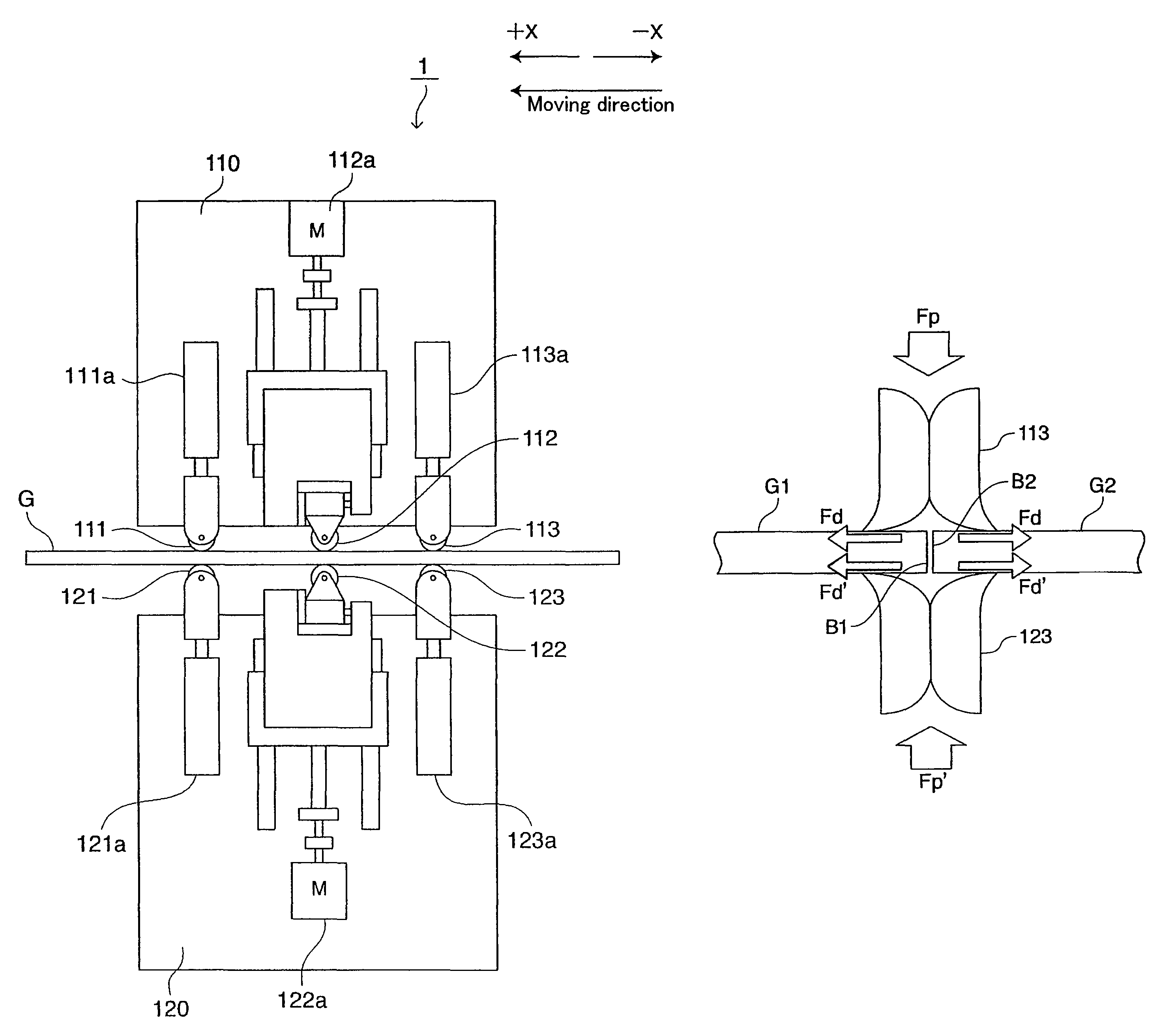
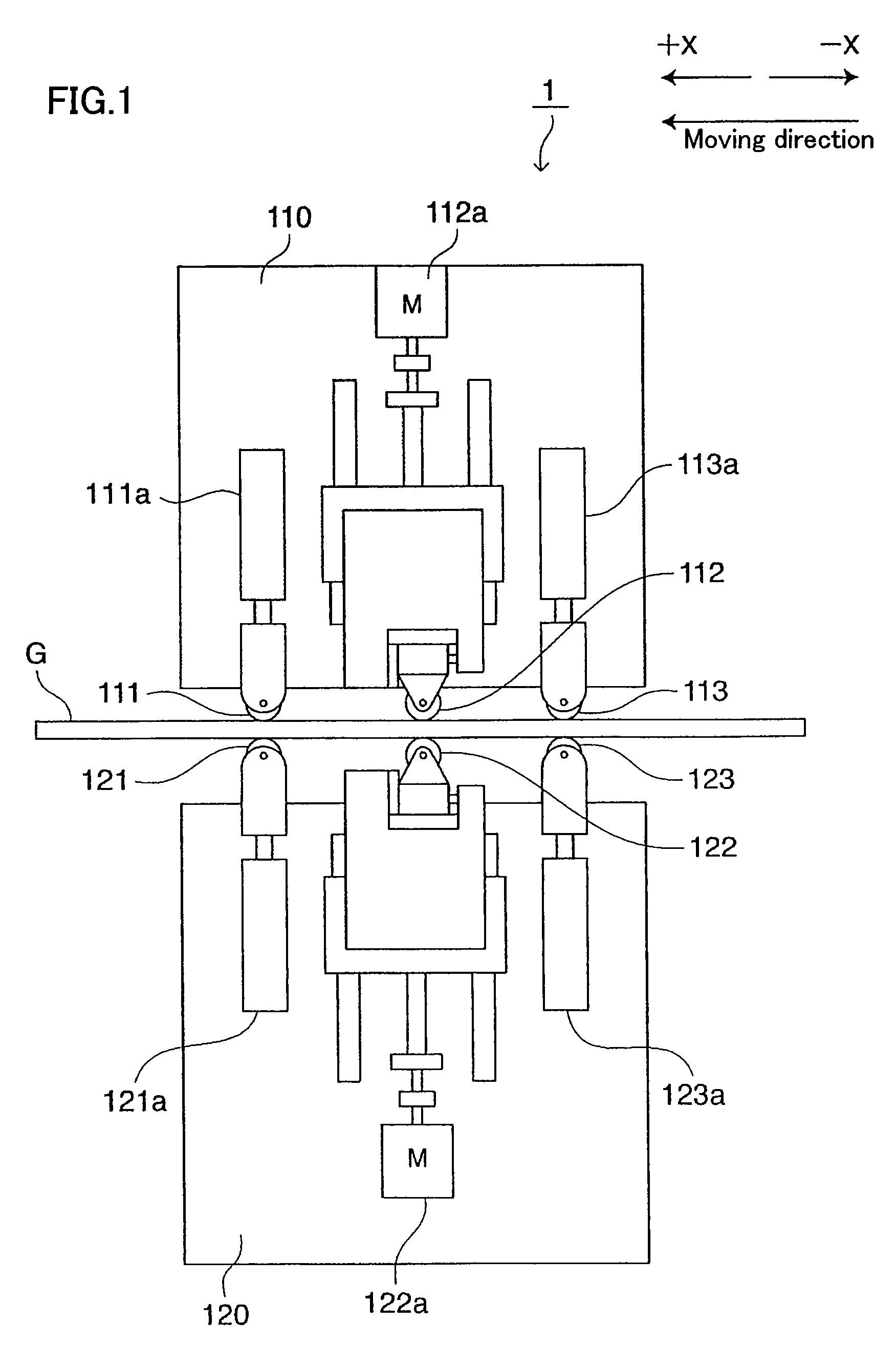
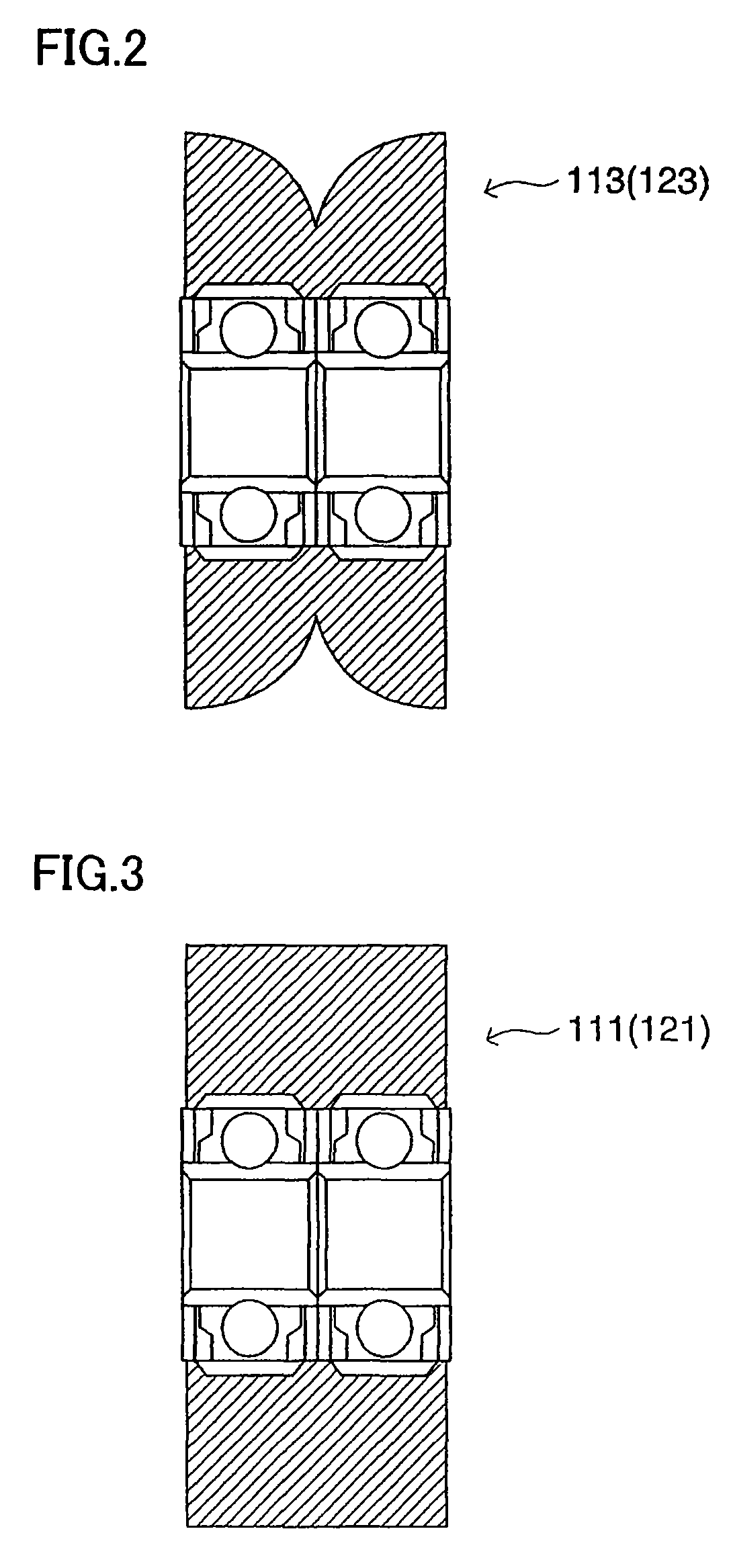
[0053]A cutting apparatus 1 according to Embodiment 1 of the present invention will be described with reference to FIG. 1. The cutting apparatus 1 shown in FIG. 1 is for performing a break step of cutting a substrate G with a scribe line formed thereon. The cutting apparatus 1 includes an upper roller holding section 110 and a lower roller holding section 120 arranged below the upper roller holding section 110. The substrate G is, for example, a brittle material substrate such as glass substrate, and the substrate G is mounted on a table 130 (see FIG. 5). The table 130 shown in FIG. 5 includes a plurality of table structuring members 130a, and the table 130 is a vacuum suctioning table functioning as a substrate holding section, wherein each of the plurality of table structuring members 130a is, for example, provided with a mechanism for holding the substrate G by vacuum-suction. The table 130 holds only side portions of the substrate G such that the lower roller holding portion 120...
embodiment 2
[0094]The cut-face separating section included in the cutting apparatus according to Embodiment 1 of the present invention described above moves the substrate portions cut in the break step in directions to separate the substrate portions from each other while cut-face separating section included in a cutting apparatus according to Embodiment 2 is characterized by moving one of cut substrate portions in an upper and lower direction, in addition to the feature of Embodiment 1.
[0095]A cutting apparatus 2 according to Embodiment 2 shown in FIG. 10 uses separating first rollers 113D (cross-sectional view thereof shown in FIG. 7) in place of the first separating roller 113 and the second separating roller 123 in the cutting apparatus 1 according to Embodiment 1 shown in FIG. 1. The first separating roller 113D arranged above the substrate G and the second separating roller 113D arranged below the substrate G are arranged on the same side (which corresponds to the substrate portion G1 whi...
embodiment 3
[0102]The cut-face separating sections included in the cutting apparatuses according to Embodiments 1 and 2 of the present invention described above have structures that the rollers or belts contacting the substrate are deformed, or the rotation axis is inclined with respect to the moving direction, so that the substrate portions cut in the break step are separated from each other. Instead thereof, a cut-face separating section included in a cutting apparatus according to Embodiment 3 is characterized by moving cut substrate portions by controlling the position of one of the cut substrate portions using a roller for pressing a surface of the substrate G and a roller having an inclined outer circumferential surface with the outer-diameter thereof gradually decreased along its axial direction to hold one of the cut substrate portions therebetween.
[0103]In a cutting apparatus 3 according to Embodiment 3 shown in FIG. 11, the first separating roller 113 and the second separating roller ...
PUM
| Property | Measurement | Unit |
|---|---|---|
| brittle | aaaaa | aaaaa |
| pressure | aaaaa | aaaaa |
| force | aaaaa | aaaaa |
Abstract
Description
Claims
Application Information
 - R&D
- Intellectual Property
- Life Sciences
- Materials
- Tech Scout
- Unparalleled Data Quality
- Higher Quality Content
- 60% Fewer Hallucinations
Browse by: Latest US Patents, China's latest patents, Technical Efficacy Thesaurus, Application Domain, Technology Topic, Popular Technical Reports.
© 2025 PatSnap. All rights reserved.Legal|Privacy policy|Modern Slavery Act Transparency Statement|Sitemap|About US| Contact US: help@patsnap.com


