Supercharge Your Innovation With Domain-Expert AI Agents!

Thermal head, printer and method for manufacturing thermal head

A technology of thermal heads and heating resistors, which is applied in printing and other directions, can solve the problems of slow response characteristics of heating resistors, longer non-heating time, and difficulty in cooling heating resistors, so as to reduce heat capacity, reduce printing speed, Effect of Power Consumption Reduction

Inactive Publication Date: 2016-01-20
SEIKO INSTR INC
View PDF1 Cites 0 Cited by
  • Summary
  • Abstract
  • Description
  • Claims
  • Application Information

AI Technical Summary

Problems solved by technology

[0006] With regard to the thermal head described in Patent Document 1, the heat capacity is reduced by the cavity portion, so that the response characteristics of the heating resistor during the heating time are rapid, but due to the heat storage effect of the supporting substrate, the heating resistor once the temperature rises It is difficult to cool the body, so the response characteristics of the heating resistor during the non-heating time are slow, and the non-heating time becomes longer

Method used


Image

  • Thermal head, printer and method for manufacturing thermal head
  • Thermal head, printer and method for manufacturing thermal head
  • Thermal head, printer and method for manufacturing thermal head

Examples


Embodiment Construction

[0047] Hereinafter, a thermal head, a printer, and a method of manufacturing the thermal head according to one embodiment of the present invention will be described with reference to the drawings.

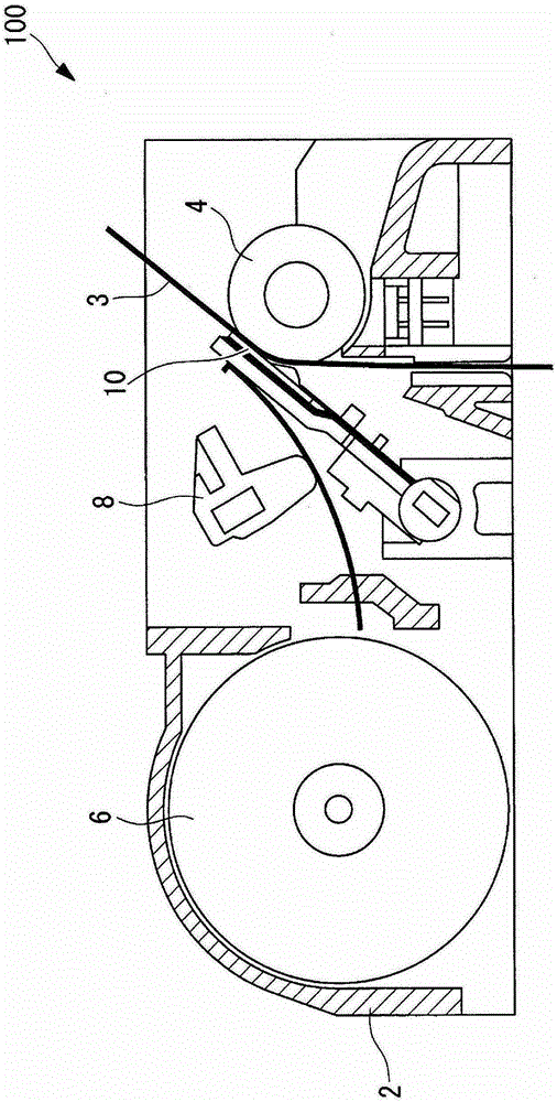
[0048] like figure 1 As shown, the thermal printer (printer) 100 of this embodiment has: a main body frame 2; a platen roller 4 arranged horizontally; a thermal head 10 facing the outer peripheral surface of the platen roller 4; The paper feeding mechanism 6 that sends out the thermal paper (thermal recording medium) 3 between the heads 10; and the pressing mechanism 8 that presses the thermal head 10 against the thermal paper 3 with a prescribed pressing force.

[0049] The thermal paper 3 and the thermal head 10 are pressed against the embossing roller 4 by the action of the pressing mechanism 8 . Thus, the load of the platen roller 4 is applied to the thermal head 10 via the thermal paper 3 . Then, printing is performed by pressing the heat generating part of the thermal head ...


PUM


Abstract

A thermal head including: a laminated substrate including a support substrate and an upper substrate at least one of which has a recess formed in a surface thereof; a heat generating resistor formed on a surface of the upper substrate in the laminated substrate at a position opposed to the recess; and a pair of electrode portions connected to each of both ends of a heat generating resistor, wherein the laminated substrate further includes: an intermediate metal layer sandwiched between the support substrate and the upper substrate and bonded thereto in a laminated state; and a surrounding metal layer formed of a metal material, the surrounding metal layer provided in contact with the intermediate metal layer and formed from a surface of the support substrate extending in a thickness direction thereof to a surface thereof opposite to a portion bonded to the upper substrate.

Description

technical field [0001] The invention relates to a thermal head, a printer and a method for manufacturing the thermal head. Background technique [0002] Conventionally, thermal heads used in thermal printers have been widely known (for example, refer to Patent Document 1). In the thermal head described in Patent Document 1, a plurality of heating resistors and electrode parts are formed on a laminated substrate of a support substrate and an upper substrate made of the same glass material, and the heating resistors are heated by supplying electric power to the electrode parts, thereby Printing on thermal recording media and the like is possible. [0003] In addition, this thermal head has a cavity portion in a region facing the heating resistor at the joint portion of the support substrate and the upper substrate, and the cavity portion functions as a heat insulating layer, thereby reducing the number of passages from the heating resistor body via the upper substrate. The p...

Claims


Application Information

Patent Timeline
Patent Type & Authority Patents(China)
IPC IPC(8): B41J2/235
CPCB41J2/3351B41J2/33545B41J2/3355B41J2/3357B41J2/33585B41J2/3359
Inventor 师冈利光顷石圭太郎东海林法宜三本木法光
Owner SEIKO INSTR INC
Features
  • R&D
  • Intellectual Property
  • Life Sciences
  • Materials
  • Tech Scout
  • Unparalleled Data Quality
  • Higher Quality Content
  • 60% Fewer Hallucinations
Learn More