Driving part structure of working vehicle

A technology for working vehicles and parts, which is applied to the layout of vehicle components and power unit cooling combined, power units, etc., can solve the problems of reduced engine cooling efficiency, maintenance of hydraulic continuously variable transmission, and difficulty in inspection operations, etc. The effect of cooling efficiency

Active Publication Date: 2013-07-03
ISEKI & CO LTD
View PDF4 Cites 1 Cited by
  • Summary
  • Abstract
  • Description
  • Claims
  • Application Information

AI Technical Summary

Problems solved by technology

[0006] However, in the prime mover of the invention described in Patent Document 1, when the outside air taken in by the fan is sent to the engine, the hydraulic continuously variable transmission may become an obstacle and reduce the cooling efficiency of the engine.
[0007] In addition, since the hydraulic continuously variable transmission is arranged between the engine and the fan, maintenance and inspection of the hydraulic continuously variable transmission are difficult

Method used


Image

  • Driving part structure of working vehicle
  • Driving part structure of working vehicle
  • Driving part structure of working vehicle

Examples


Embodiment Construction

[0063] Hereinafter, embodiments of the present invention will be described in detail with reference to the drawings. In addition, although the direction is shown and demonstrated conveniently for easy understanding, the structure is not limited by these.

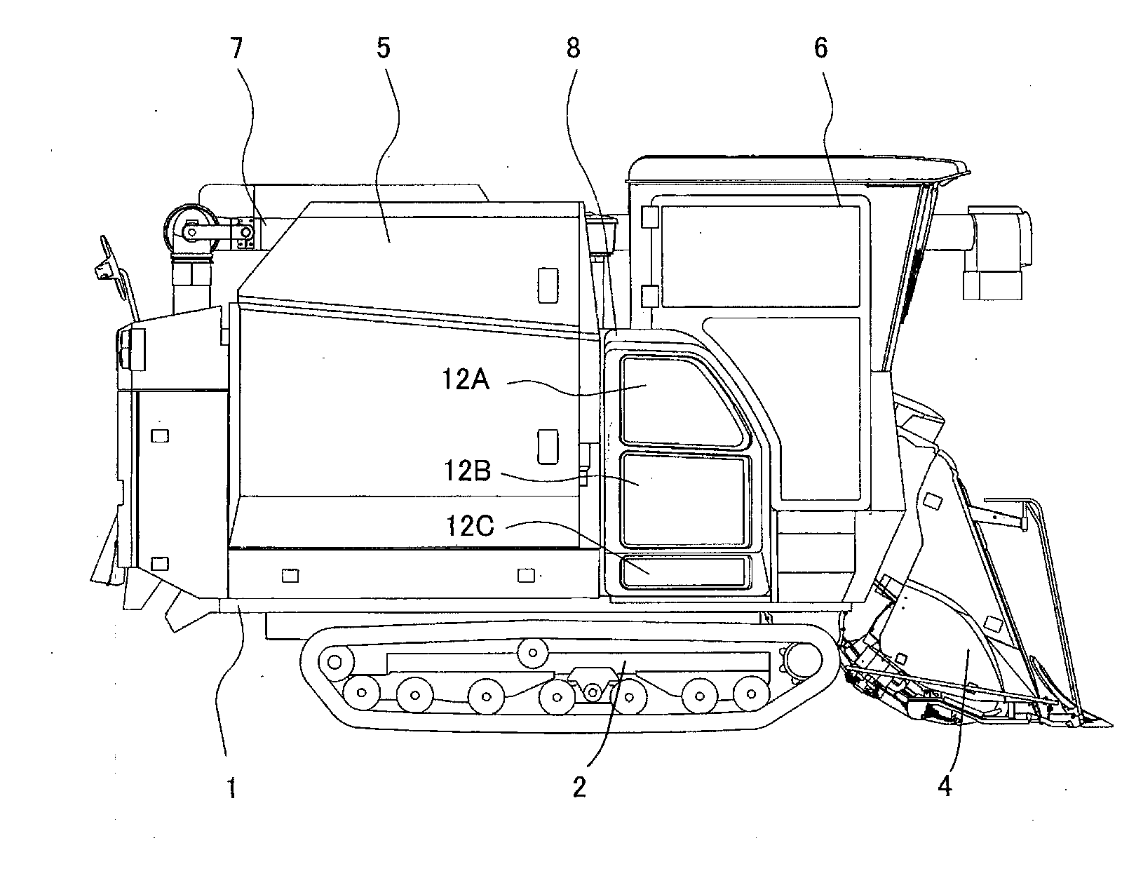
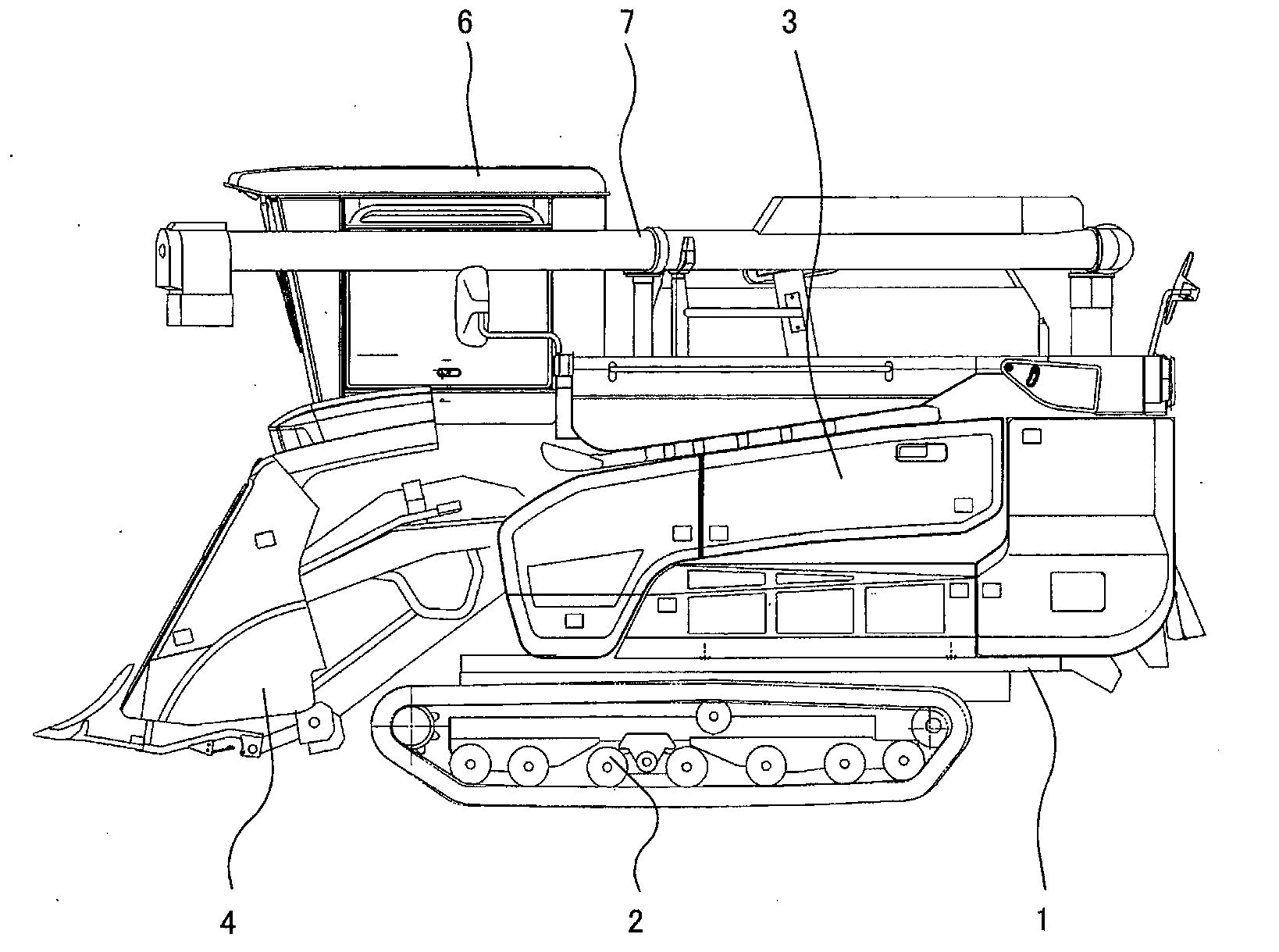
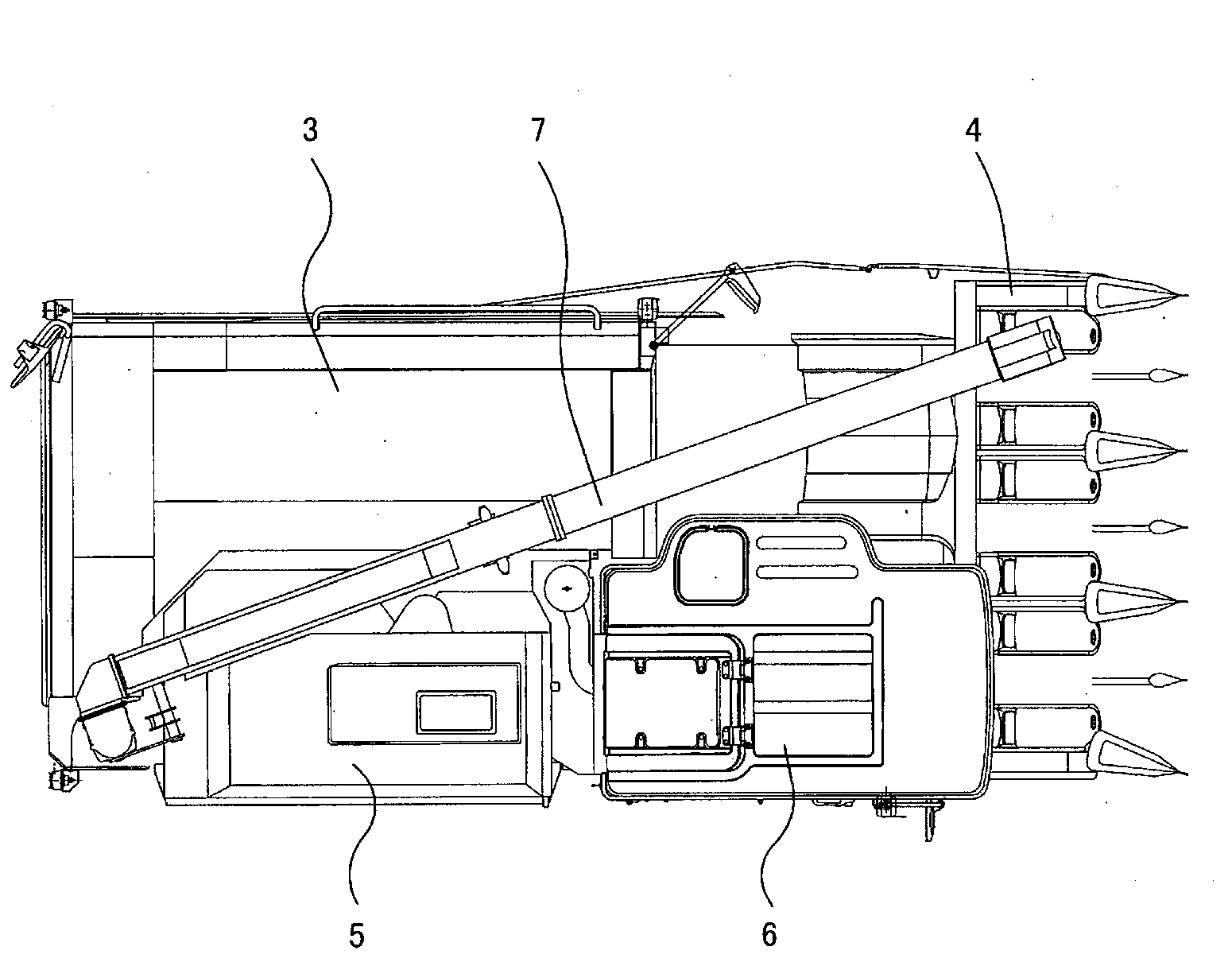
[0064] Such as Figure 1 to Figure 3 As shown, in the combine harvester, a walking device 2 consisting of a pair of left and right crawlers walking on the soil surface is provided below the body frame 1, and a threshing machine for threshing and screening is provided on the upper left side of the body frame 1. The device 3 is provided with a harvesting device 4 for harvesting grain stalks in the field in front of the threshing device 3 . The grains threshed and screened by the threshing device 3 are accumulated in the grain tank 5 provided on the right side of the threshing device 3 , and the stored grains are discharged to the outside by the discharge cylinder 7 . Further, a cab 6 is provided on the upper right side of th...


PUM


Abstract

The invention provides a driving part structure of an operation vehicle. The cooling efficiency of a motor of the driving part structure is outstanding, and the structure can be maintained and checked easily. The driving part structure is characterized in that a hydraulic continuously variable transmission (30) enabling the driving force of the motor (20) to be changed and output to the side of a fan (40) is configured at a position in a motor cabinet (8) close to the inner side of a motor body. By device of the speed changing action in the forwarding direction and the reversing direction of the hydraulic continuously variable transmission (30), the structure can be switched to a cooling state and a dedusting state automatically; and the cooling state is a state wherein external air can be suctioned from the outer side of a filtering body (12) to the inner side as the hydraulic continuously variable transmission (30) is forwardly rotated to drive the fan (40); and the dedusting state is a state wherein air is exhausted from the inner side of the filtering body (12) to the outer side as the hydraulic continuously variable transmission (30) reverses to drive the fan (40).

Description

technical field [0001] The present invention relates to the structure of the driving part of the work vehicle. Background technique [0002] In order to save space in an engine room of a combine harvester, Patent Document 1 discloses a structure of a motive part in which a radiator, a fan, a hydraulic continuously variable transmission, and an engine are arranged in parallel in the engine room from the outer side of the machine body toward the inner side. [0003] prior art literature [0004] patent documents [0005] Patent Document 1: Japanese Patent Laid-Open No. 2008-88823 [0006] However, in the prime mover of the invention described in Patent Document 1, when the outside air taken in by the fan is sent to the engine, the hydraulic continuously variable transmission may hinder the cooling efficiency of the engine. [0007] In addition, since the hydraulic continuously variable transmission is arranged between the engine and the fan, maintenance and inspection work ...

Claims


Application Information

Patent Timeline
Patent Type & Authority Applications(China)
IPC IPC(8): F01P5/04
CPCB60K11/04F01P3/18F01P5/02F01P5/04F01P11/10F01P11/12F02B67/06
Inventor 藤田靖
Owner ISEKI & CO LTD
Why Eureka
Try Eureka