Quality detection method of boring on printed circuit board

A technology for printed circuit boards and detection methods, which is applied to measuring devices, instruments, scientific instruments, etc., can solve problems such as high scrap rate, affecting processing steps, waste of raw materials, etc., to reduce drilling scrap rate and improve processing quality efficiency and reduce production costs

Active Publication Date: 2013-07-03
NEW FOUNDER HLDG DEV LLC +1
View PDF4 Cites 26 Cited by
  • Summary
  • Abstract
  • Description
  • Claims
  • Application Information

AI Technical Summary

Problems solved by technology

However, for some printed circuit boards (including single-piece printed circuit boards) with small batch production volume, if the drilling deviation occurs on the first board, it means that the scrap rate must remain high; and for those material costs For higher-frequency printed circuit boards, if the drilling deviation of the first board is found during the inspection, it means a great waste of raw materials, which means that the production cost will increase significantly
[0005] As can be seen from the above, ...

Method used


Image

  • Quality detection method of boring on printed circuit board
  • Quality detection method of boring on printed circuit board
  • Quality detection method of boring on printed circuit board

Examples


Embodiment 1

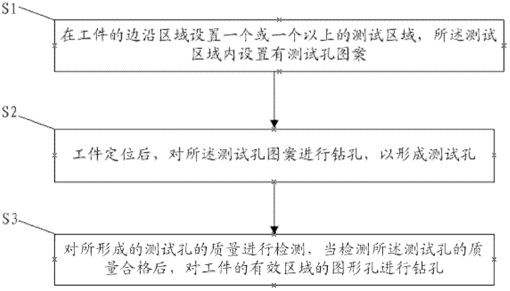
[0035] Such as figure 1 As shown, in the present embodiment, the detection method of drilling quality on the printed circuit board comprises the following steps:

[0036] S1) One or more test areas are set in the edge area of ​​the workpiece, and test hole patterns are set in the test areas.

[0037] Such as Figure 5 As shown, the workpiece includes an edge region 14 and an active region 15 . There are one or more test areas, and each test area is distributed on two or more sides of the edge area of ​​the workpiece. In this embodiment, the shape of the workpiece is a rectangular plate, and a test area 20 is respectively set at the four corners of the edge area of ​​the workpiece, and the four test areas 20 are arranged on the four sides of the workpiece in pairs. The positions of the two test areas separated on the two opposite sides correspond to each other, so as to ensure that the drilling quality of the entire plate surface of the workpiece can be tested.

[0038] In ...

Embodiment 2

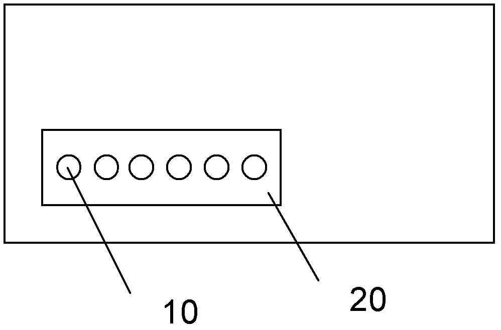
[0061] Such as Figure 6 As shown, the difference between this embodiment and Embodiment 1 is that there are 2 test areas in the edge area of ​​the workpiece in this embodiment, which are distributed at the diagonal positions of the workpiece, and 4 test areas are respectively arranged in each test area. 10 test holes. Compared with Embodiment 1, this embodiment is suitable for the inspection of the drilling quality of PCB boards with relatively simple graphic lines and fewer graphic holes in the effective area of ​​the workpiece.

[0062] The pattern of the test hole, the setting of the test hole and the detection method in this embodiment are the same as those in Embodiment 1, and will not be repeated here.

[0063] In embodiments 1 and 2, using the detection method of the drilling quality to drill the test hole in the edge area of ​​the workpiece is different from the pattern hole drilling in the effective area of ​​the workpiece, even if holes appear in the process of dri...


PUM


Abstract

The invention provides a quality detection method of boring on a printed circuit board, which comprises the following steps: 1) setting one or more test areas at edge area of a workpiece, arranging a test hole pattern in the test area; 2) positioning the workpiece, boring according to the test hole pattern to form a test hole; and 3) detecting the quality of the formed test hole, and boring the pattern aperture on an effective area of the workpiece when the detected test hole is qualified,. The boring quality detection method can effectively reduce the boring disability rate of the workpiece, product processing yield rate during a boring technology can be increased, and the production cost is reduced.

Description

technical field [0001] The invention belongs to the technical field of printed circuit board production, and relates to a method for detecting the quality of drilling holes on a printed circuit board. Background technique [0002] During the processing of printed circuit boards (PCB boards), it involves multiple process steps such as material cutting-inner layer production-lamination-drilling-copper sinking-outer layer production-surface coating-shape processing, etc., in each process After the process is completed, corresponding inspections are required to ensure the quality of each process step. [0003] Wherein, the process steps of drilling include steps such as lamination pins-upper PCB board-drilling-bottom PCB board-detection, in the drilling process steps of the prior art, first in the edge area of ​​the workpiece (i.e. outside the workpiece circuit pattern) area) to drill the positioning hole, and then use the positioning hole for positioning, and then drill the gr...

Claims


Application Information

Patent Timeline
IPC IPC(8): G01N23/00
Inventor 陈显任黄承明
Owner NEW FOUNDER HLDG DEV LLC
Why Eureka
Try Eureka