
High voltage direct current control switch

A technology for controlling switches and high-voltage DC, applied in the field of switches, can solve problems such as contact burnout, inability to work, strong arcing of mechanical contacts, etc.

Active Publication Date: 2013-07-03
SHENZHEN GOLD POWER TECH
View PDF4 Cites 7 Cited by
  • Summary
  • Abstract
  • Description
  • Claims
  • Application Information

AI Technical Summary

Problems solved by technology

On the high-voltage DC side, mechanical switches are generally used for distribution, but when the mechanical switch is closed or disconnected, a strong arc will be generated between the mechanical contacts; if no corresponding arc suppression measures are taken, the contacts will burn out and fail to work. A flaming switch could even start a fire

Method used


Image

  • High voltage direct current control switch
  • High voltage direct current control switch
  • High voltage direct current control switch

Examples


Embodiment 1

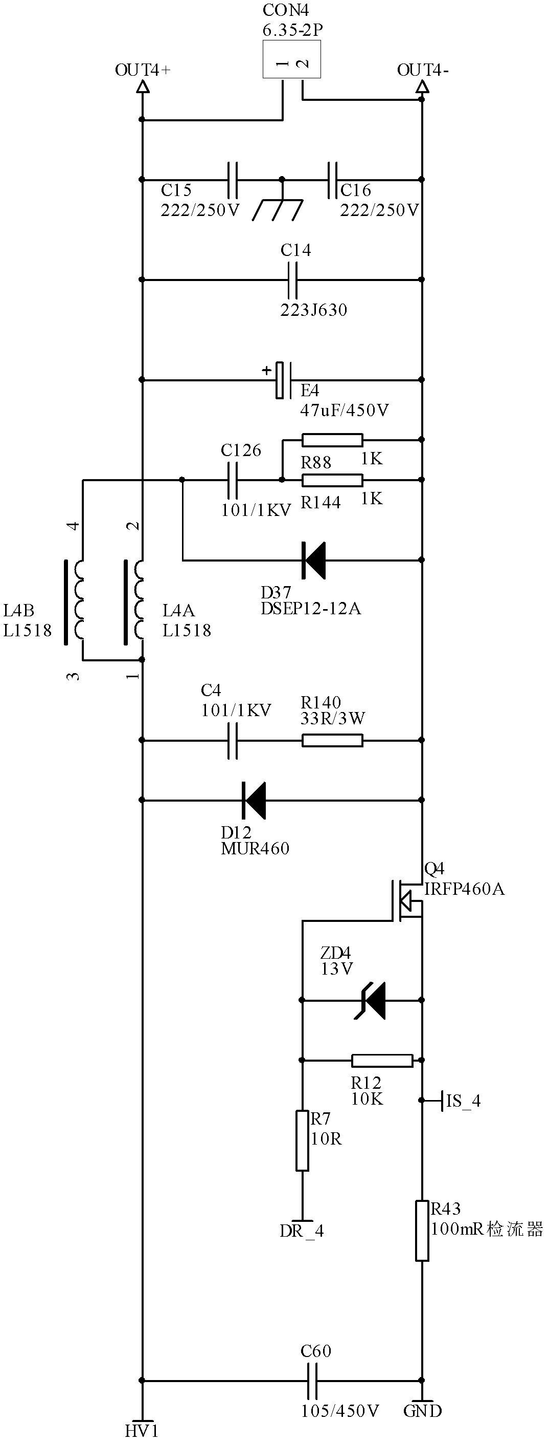
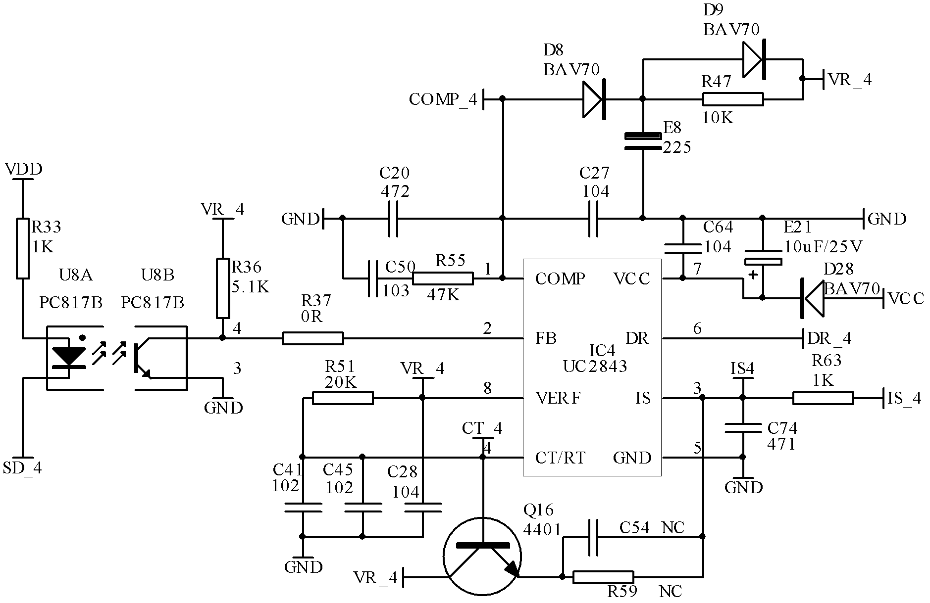
[0028] Embodiment 1, this embodiment is a control switch arranged at the output end of a high-voltage DC power supply, such as figure 1 As shown: the high-voltage DC control switch in this embodiment is set at the output end of the high-voltage DC power supply; the output end of the high-voltage DC power supply includes the power supply anode HV1 and the power supply cathode GND; after passing through the high-voltage DC control switch, the output is the output positive pole OUT+ and the output negative pole OUT -; including MOSFET electronic switching power circuits such as figure 2 As shown, the control circuit that controls the opening and closing of the MOSFET electronic switching power circuit; the MOSFET electronic switching power circuit is set between the power supply anode HV1 and the power supply cathode GND and the output positive pole OUT+ and the output negative pole OUT-, and the control power supply anode HV1 and the output positive pole OUT+, the connection an...


PUM


Abstract

The invention aims at providing a high voltage direct current control switch which is arranged at an output end of a high voltage direct current power supply and comprises an MOSFET (Metal-Oxide -Semiconductor Field Effect Transistor) electronic switch power circuit, and a control circuit for controlling opening and closing of the MOSFET electronic switch power circuit, wherein the control circuit comprises a current sampling circuit for sampling output current of the high voltage direct current power supply, a switch control circuit generating control signals to control the opening and closing of the MOSFET electronic switch power circuit, and a singlechip. The high voltage direct current control switch comprises the MOSFET electronic switch circuit and the MCU (Micro Controller Unit) intelligent control circuit; the MOSFET electronic switch circuits can be in parallel connection to form a multiway switch; and the whole scheme can realize an intelligent electronic switch which achieves multiple parallel switches, spark-free switch motion and mutual delay among the switches, and has functions of short-circuit protection, self recovery after removal of a short-circuit fault, and the like.

Description

technical field [0001] The invention relates to the field of switches, in particular to an electronic switch arranged at the output end of a DC high-voltage output power supply to control the connection or disconnection of a load. Background technique [0002] At present, communication equipment generally adopts centralized power supply. After the alternating current is rectified and filtered in the computer room to form direct current high voltage (200~~400VDC), it is transmitted to each communication terminal through a dedicated power line for use by the communication terminal. On the high-voltage DC side, mechanical switches are generally used for distribution, but when the mechanical switch is closed or disconnected, a strong arc will be generated between the mechanical contacts; if no corresponding arc suppression measures are taken, the contacts will burn out and fail to work. A burning switch could even start a fire. Contents of the invention [0003] The present i...

Claims


Application Information

Patent Timeline
Patent Type & Authority Applications(China)
IPC IPC(8): G05B19/042
Inventor 廖肇军张建光
Owner SHENZHEN GOLD POWER TECH
Learn More