Barcode reading and decoding module and handheld electronic device

A decoding module and barcode technology, which is applied in the field of barcode recognition, can solve the problems of high power consumption, low cost of components, and small size, and achieve the effect of the most simplified components, low power consumption, and small size

Active Publication Date: 2015-10-28
FUJIAN NEWLAND AUTO ID TECH CO LTD
View PDF6 Cites 0 Cited by
  • Summary
  • Abstract
  • Description
  • Claims
  • Application Information

AI Technical Summary

Problems solved by technology

[0007] To sum up, the overall structure of the existing barcode reading module needs to be equipped with circuit boards of image sensor chips, optical lenses, lighting circuit boards and other components in order to fix them and prevent external non-imaging light from affecting image transmission. Sensor chip image quality
Due to the need to carry more components, even including the fixing of various circuit boards, the structural size of the entire barcode reading module is difficult to achieve 1000mm 3 Therefore, it has defects such as large size, high power consumption, many components, and high cost, which is not conducive to the miniaturization design of the barcode reading module
If it is necessary to further incorporate the decoding function into the decoding and reading module to form a barcode reading and decoding module, it is even more difficult to achieve a miniaturized design of the overall module
[0008] Therefore, the main purpose of the present invention is to solve the problem that the current barcode reading and decoding module is difficult to achieve extremely small size, extremely low power consumption, the most simplified components and extremely low cost

Method used


Image

  • Barcode reading and decoding module and handheld electronic device
  • Barcode reading and decoding module and handheld electronic device
  • Barcode reading and decoding module and handheld electronic device

Examples


Embodiment Construction

[0035] The present invention relates to a barcode reading and decoding module, which is mainly used to identify one-dimensional barcodes or two-dimensional barcode images. In order to make the purpose, technical solutions and advantages of the present invention clearer, the following describes in detail with reference to the accompanying drawings:

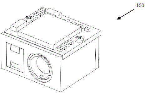
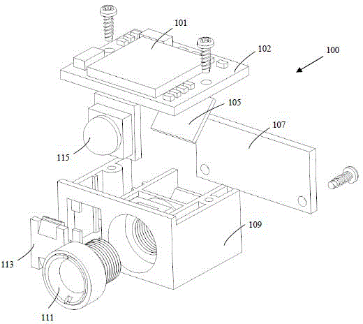
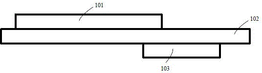
[0036] Reference Figure 1a , 1b As shown, the barcode reading and decoding module 100 of the present invention includes a barcode processing chip 101, a first circuit board 102, a reflector 105, a second circuit board 107, a bracket 109, a lens module 111, a special-shaped lens 113, and a light source 115. The bracket 109 is used to support and fix the first circuit board 102, the reflector 105, the second circuit board 107, the lens module 111, the special-shaped lens 113 and the light source 115. In addition, the first circuit board 102 and the second circuit board 107 are fixed to the upper and rear of the bracket 109 by screws, res...


PUM


Abstract

The invention provides a bar code reading and decoding module and a handheld electronic device. The bar code reading and decoding module comprises a circuit board, a luminescent source, a specially-shaped lens and a bracket, wherein the circuit board comprises a bar code processing chip and an image sensing chip which are respectively located at different sides of the circuit board, the image sensing chip is a complementary metal oxide semiconductor chip and is used for collecting images, and the bar code processing chip is used for carrying out bar code decoding on the images; the luminescent source is a light emitting diode and is located behind the specially-shaped lens; the specially-shaped lens comprises a light equalization region and a light condensation region, and a lighting pattern and an aiming pattern are formed by the luminescent source through the specially-shaped lens; and the bracket is used for loading the circuit board, the luminescent source and the special-shape lens. Compared with the prior art, the bar code reading and decoding module has the beneficial effects of small size, low power dissipation, few devices and low cost.

Description

Technical field [0001] The invention relates to the field of bar code recognition, in particular to a bar code reading and decoding module and a handheld electronic device. Background technique [0002] Barcode scanner is an input device that uses optoelectronic principles to convert barcode information into computer-acceptable information. It is often used in libraries, hospitals, bookstores, and supermarkets as an input method for rapid registration or settlement. The image or bar code information on the printed matter is directly read and input into the online system. Therefore, the barcode scanner must at least have the functions of reading and decoding, and the prior art mostly uses an imaging module (imaging module, imaging head) with a decoding circuit board to achieve the aforementioned functions. [0003] The electronic circuit architecture of the existing barcode reading module mainly uses a microprocessor (CPU) with a random access memory (RAM) and flash memory (FLASH) ...

Claims


Application Information

Patent Timeline
Patent Type & Authority Patents(China)
IPC IPC(8): G06K7/10
Inventor 施晓迪罗烽刘继军
Owner FUJIAN NEWLAND AUTO ID TECH CO LTD
Why Eureka
Try Eureka