
A charging and discharging control circuit for a super-capacitor and an energy storage unit and a method thereof

A technology of supercapacitor and energy storage unit, which is applied in the direction of battery circuit devices, electrical components, circuit devices, etc., and can solve the problems of lack of comprehensiveness and diversification

Inactive Publication Date: 2013-07-03
GRAND POWER SYST TECH
View PDF0 Cites 8 Cited by
  • Summary
  • Abstract
  • Description
  • Claims
  • Application Information

AI Technical Summary

Problems solved by technology

[0004] However, although the above two types of application technologies have both innovative and practical features, they have not seen their comprehensive and diversified development. There is room for innovation and leap forward in the matching technology and application circuit design between the two.

Method used


Image

  • A charging and discharging control circuit for a super-capacitor and an energy storage unit and a method thereof
  • A charging and discharging control circuit for a super-capacitor and an energy storage unit and a method thereof
  • A charging and discharging control circuit for a super-capacitor and an energy storage unit and a method thereof

Examples


Embodiment Construction

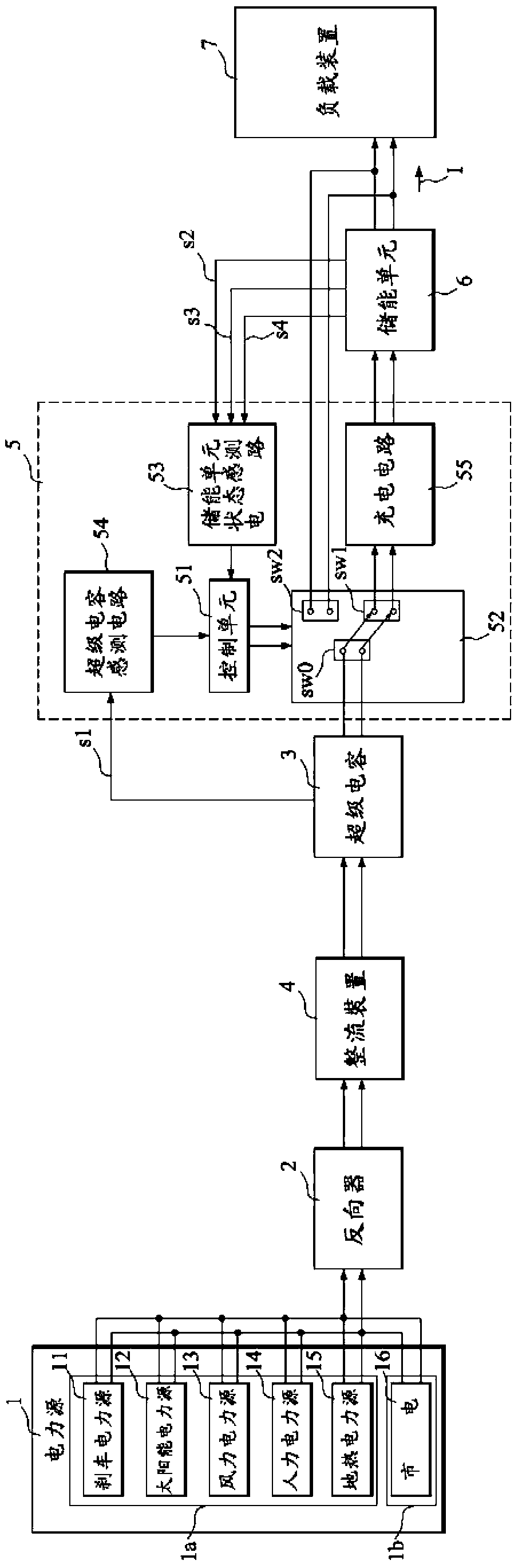
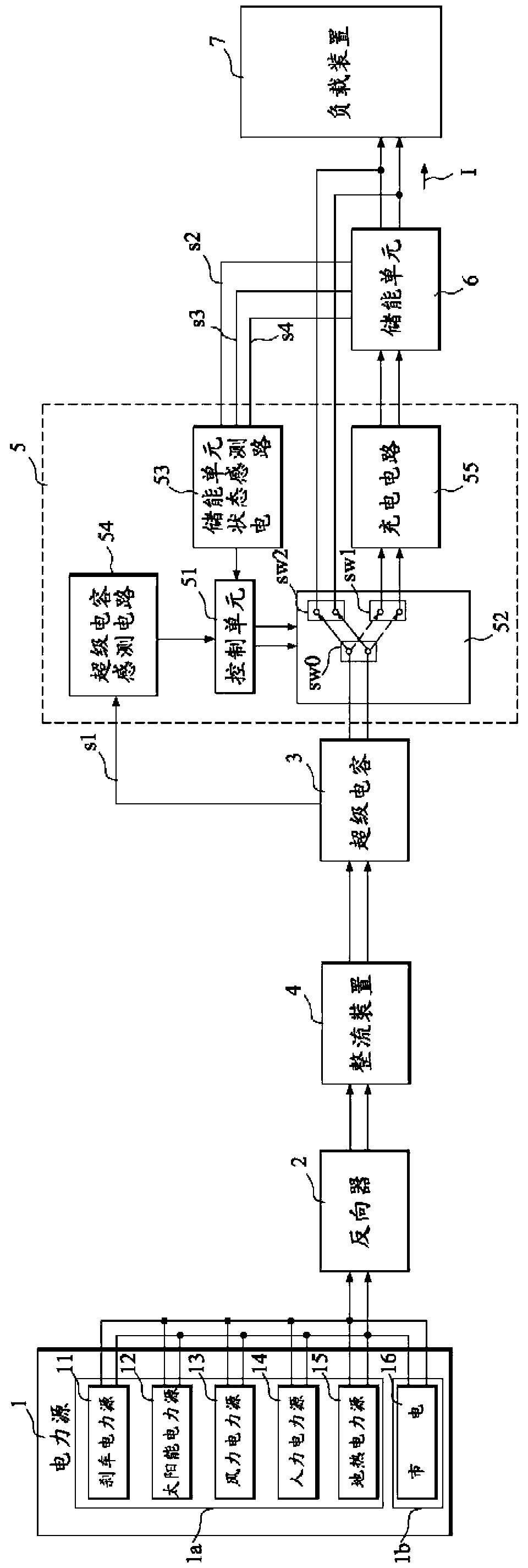
[0064] see figure 1 As shown, the cascaded charge control circuit of the supercapacitor and energy storage unit of the present invention mainly includes at least one power source 1, at least one supercapacitor 3, a charge and discharge control circuit 5, and at least one energy storage unit 6 ; Wherein the charge and discharge control circuit 5 includes a control unit 51, at least one path switching unit 52, an energy storage unit state sensing circuit 53 and a super capacitor sensing circuit 54; and the path switching unit 52 includes at least one The common connection end sw0, a charging path connection end sw1, and a discharge path connection end sw2. In different embodiments, the energy storage unit sensing circuit 53 and the supercapacitor sensing circuit 54 can also be arranged outside the charge and discharge control circuit 5 of the present invention, and then electrically connected to the charge and discharge control circuit 5 instead of Such as figure 1 As shown, i...


PUM


Abstract

A charging and discharging control circuit for a super-capacitor and an energy storage unit, in particular refers to a charging and discharging control circuit both having a cascade charging control mode, discharging control mode, and recharging control mode switching function, and a parallel type charging and discharging control mode switching function. The charging and discharging control circuit mainly includes at least one power source, at least one super-capacitor, a charging and discharging control circuit, and at least one energy storage unit; wherein the charging and discharging control circuit comprises a control unit, at least one path switching unit, a supercapacitor state sensing circuit and a storage unit condition sensing circuit; and the path switching unit comprises at least one common connection terminal, at least one charging path connecting terminal and at least one discharging path connecting terminal. The control circuit has switchable functions of protecting the charging and power suppling in parallel .

Description

technical field [0001] The invention relates to a charging and discharging control circuit for a supercapacitor and an energy storage unit, in particular to a switching function of a cascade charging control mode, a discharge control mode and a recharging control mode, and a parallel charging control circuit. The control circuit of the discharge control mode switching function. Background technique [0002] The so-called super capacitor is characterized in that in addition to its large capacity, it can temporarily store a considerable amount of electrical energy. It is not only reversible, but also can store and release energy in a short time. It is a high power density, energy density In recent years, a new type of hybrid supercapacitor battery has both the functions and characteristics of batteries; compared with supercapacitors, general energy storage units cannot withstand high-current charging in a short period of time. The release of high-current electric energy, and ...

Claims


Application Information

Patent Timeline
IPC IPC(8): H02J7/00
Inventor 周宪忠杨亮达
Owner GRAND POWER SYST TECH
Learn More