Electric rotary machine

A technology for rotating electrical machines and rotors, applied in electrical components, electromechanical devices, electrical components, etc., to solve complex problems, reduce cooling fluid flow pressure, and increase manufacturing costs.

Inactive Publication Date: 2013-07-03
DENSO CORP
View PDF6 Cites 10 Cited by
  • Summary
  • Abstract
  • Description
  • Claims
  • Application Information

AI Technical Summary

Problems solved by technology

However, when a large amount of cooling fluid is supplied into the cooling fluid passage, the structure of the cooling fluid passage disclosed in the first patent document is insufficient to sufficiently reduce the flow pressure of the cooling fluid of the spiral groove.
The first patent document also has the disadvantage of increased manufacturing costs, since the structure of the helical groove requires the execution of complex machining procedures
This increases the manufacturing cost

Method used


Image

  • Electric rotary machine
  • Electric rotary machine
  • Electric rotary machine

Examples


Embodiment Construction

[0027] Hereinafter, various embodiments of the present invention will be described with reference to the accompanying drawings. In the following description of various embodiments, the same drawing text or numerals indicate the same or equivalent components throughout the several drawings.

[0028] first exemplary embodiment

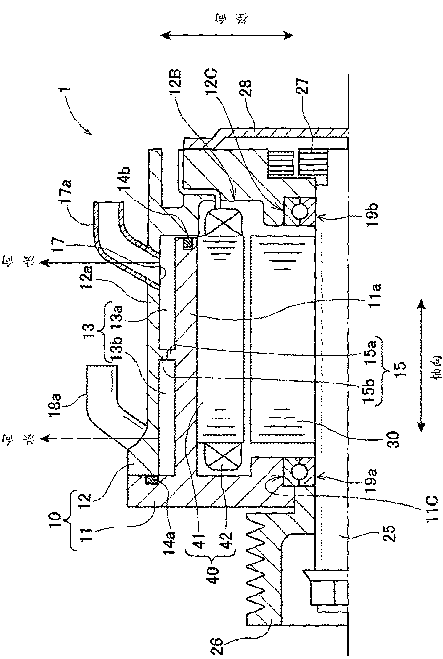
[0029] will now refer to Figure 1 to Figure 8A , Figure 8B and Figure 8C A description is given of the rotating electric machine 1 according to the first exemplary embodiment of the present invention.

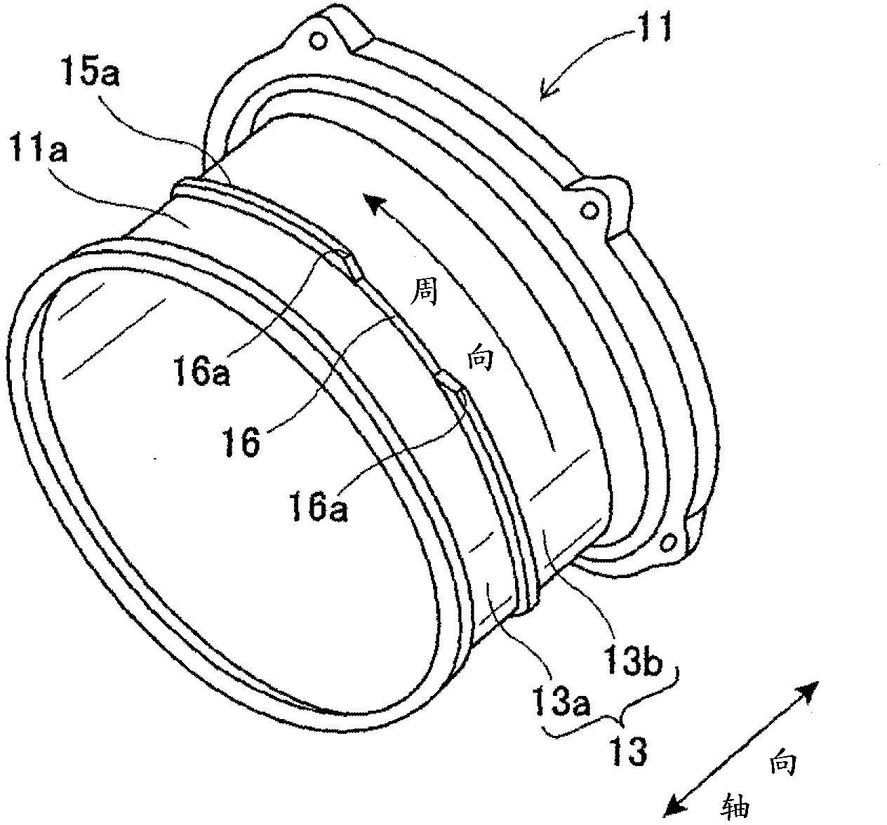
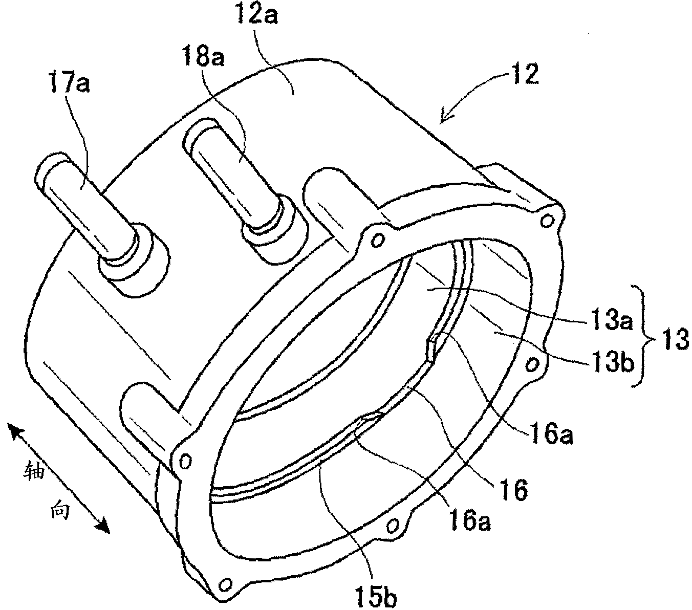
[0030] figure 1 is a view showing a partial section of the upper half in the axial direction of the rotary electric machine 1 according to the first exemplary embodiment of the present invention. figure 2 is based on figure 1 A perspective view of the first motor frame 11 among the motor frames 10 of the rotating electric machine 1 of the first exemplary embodiment shown in . image 3 is based on figure 1 A perspective view of the second motor...


PUM


Abstract

An electric rotary machine has a motor frame having a cooling fluid passage, a rotary shaft rotatably supported by the motor frame, a rotor fixed to the rotary shaft, and a stator. The stator has a core having a ring shape and a stator winding wound around the core. The stator core is arranged to face an outer periphery of the rotor in a radial direction. An inlet section and an outlet section are formed in the motor frame. Cooling fluid is introduced into the cooling fluid passage through the inlet section and discharged from the outlet section. A partition wall section is formed on the motor frame and divides the cooling fluid passage into a cooling fluid inlet passage and a cooling fluid outlet passage. Through an opening formed in the partition wall section, the cooling fluid inlet passage and the cooling fluid outlet passage communicate with each other.

Description

technical field [0001] The present invention relates to a rotating electrical machine usable as an electric motor as well as a generator in motor vehicles and the like. Background technique [0002] There are conventional rotating electrical machines which are generally well known. Such a rotating electric machine includes a rotating shaft, a rotor and a stator. The rotating shaft is rotatably supported by a cylindrical motor frame. The rotor is fixed to the rotating shaft and disposed in the motor frame. The stator has a stator core and stator windings. The stator core has an annular shape and is supported by the motor frame. The stator core is disposed at the outer periphery of the rotor to face the rotor in a radial direction of the rotor. Stator windings are wound around the stator core. For example, since the stator has a high temperature due to thermal energy when the rotating electric machine generates electric power or outputs its output torque, the first paten...

Claims


Application Information

Patent Timeline
Patent Type & Authority Applications(China)
IPC IPC(8): H02K9/19H02K5/20
CPCH02K5/203H02K9/193
Inventor 武井俊博
Owner DENSO CORP
Why Eureka
Try Eureka