Video monitoring system and video monitoring method based on optical fiber interface

A technology of video surveillance system and optical fiber interface, which is applied in TV systems, closed-circuit TV systems, TVs and other directions adapted to optical transmission. and other problems, to achieve good visual viewing effect, good visual effect, and avoid the loss of detailed information.

Active Publication Date: 2013-07-03
706 INST SECOND RES INST OF CHINAAEROSPACE SCI & IND +1
View PDF4 Cites 15 Cited by
  • Summary
  • Abstract
  • Description
  • Claims
  • Application Information

AI Technical Summary

Problems solved by technology

[0009] The purpose of the present invention is to provide a video monitoring system and monitoring method based on an optical fiber interface, which is used to solve the problem that the existing technology cannot guarantee real-time monitoring, image quality loss, image intelligent analysis, high-definition network cameras with poor reliability and extremely low maintenance. It is inconvenient and the problem that the high-definition network camera cannot be transmitted over a long distance

Method used


Image

  • Video monitoring system and video monitoring method based on optical fiber interface
  • Video monitoring system and video monitoring method based on optical fiber interface
  • Video monitoring system and video monitoring method based on optical fiber interface

Examples


Embodiment Construction

[0050] The present invention will be described in detail below in conjunction with the accompanying drawings and specific embodiments, but not as a limitation of the present invention.

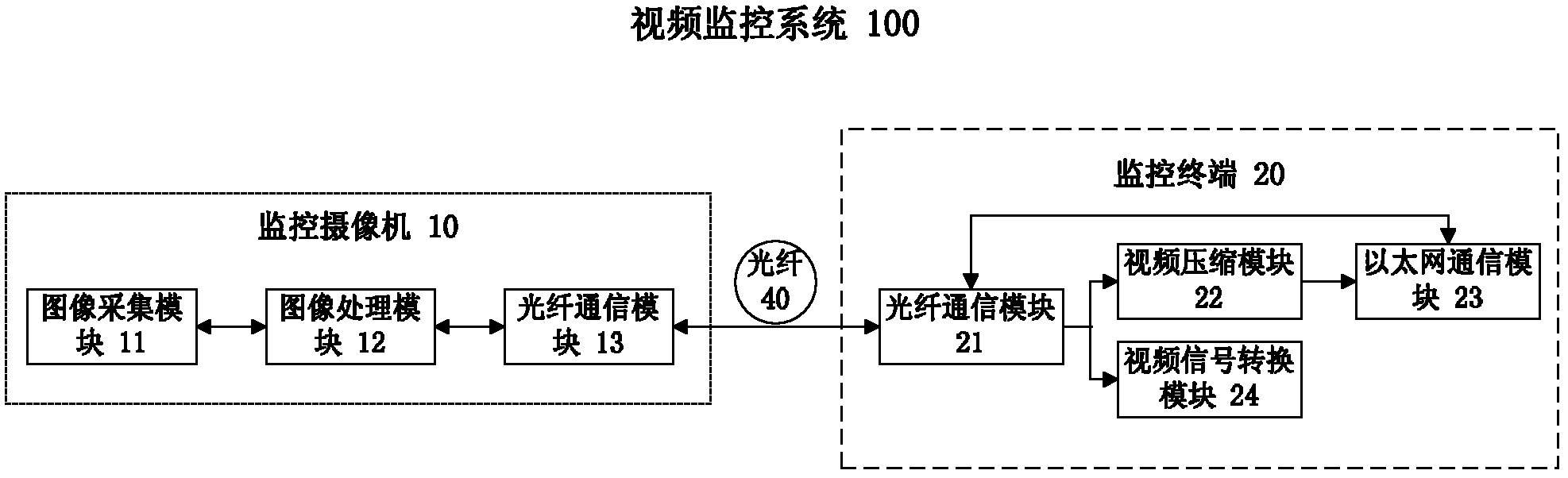
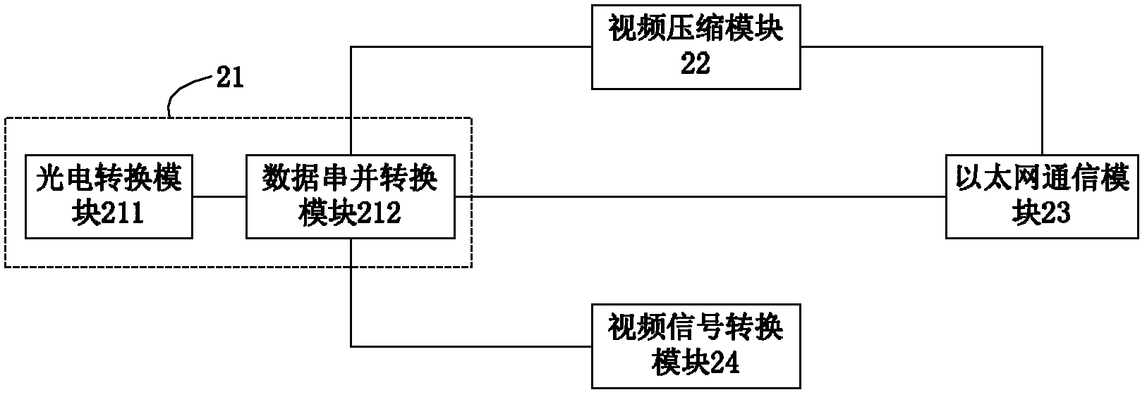
[0051] Such as figure 1As shown, it is a structural diagram of the video monitoring system based on the optical fiber interface of the present invention. The video monitoring system 100 includes a monitoring camera 10 and a monitoring terminal 20 .

[0052] Further, the surveillance camera 10 and the surveillance terminal 20 are connected through an optical fiber (optical fiber interface) 40 to form a video surveillance system 100 .

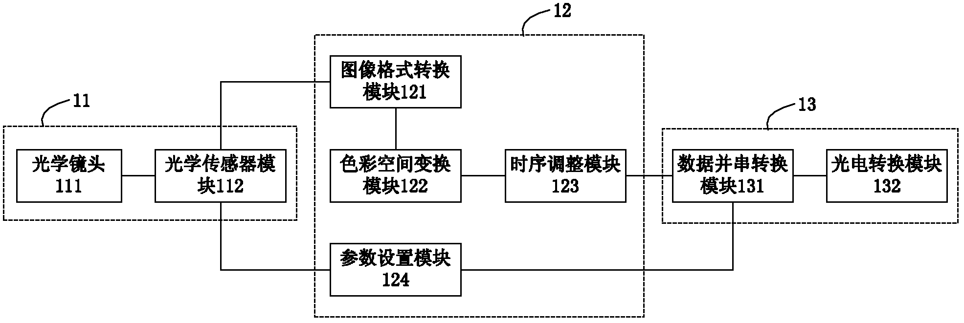
[0053] Further, the surveillance camera 10 includes an image acquisition module 11 , an image processing module 12 and an optical fiber communication module 13 . The image acquisition module 11 is connected with the image processing module 12 ; the image processing module 12 is connected with the optical fiber communication module 13 .

[0054] In the surveill...


PUM


Abstract

The invention discloses a video monitoring system and a video monitoring method based on an optical fiber interface. The system comprises a monitoring camera and a monitoring terminal, wherein the monitoring camera is connected with the monitoring terminal by the optical fiber interface; the monitoring camera transmits a non-compressed image to the monitoring terminal; the delay of the monitoring camera is far shorter than that of the existing network monitoring camera; the transmitted non-compressed image is free from image detail loss, thereby facilitating video analysis; an optical fiber communication module is embedded into the monitoring camera, so that the monitoring camera can be used for long-distance transmission; and video compression processing is conducted at the monitoring terminal, thereby facilitating centralized maintenance. The video monitoring system realizes video monitoring.

Description

technical field [0001] The invention relates to the field of security monitoring system equipment, in particular to a video monitoring system based on an optical fiber interface and a monitoring method thereof. Background technique [0002] In recent years, with the advancement of science and technology, the security industry is also developing rapidly. At present, the monitoring system has gone through three stages: analog monitoring, digital monitoring, and network monitoring. The resolution of surveillance cameras has also evolved from standard definition to high definition (HD) and full high definition (Full HD). [0003] The current high-definition network camera transmits the compressed video data to the monitoring terminal through Ethernet. The monitoring terminal stores the compressed video data transmitted by the high-definition network camera, and decompresses it for display. [0004] However, there are at least the following problems in the high-definition netwo...

Claims


Application Information

Patent Timeline
Patent Type & Authority Applications(China)
IPC IPC(8): H04N7/18H04N7/22H04N7/26H04N9/64
Inventor 裴彦杰苏威积肖鹏张春杰林秀春陈攀白松何毅黄敏君黄传鹤黄晶
Owner 706 INST SECOND RES INST OF CHINAAEROSPACE SCI & IND
Why Eureka
Try Eureka