Optical fiber connector component and optical fiber connector provided with optical fiber connector component

一种光纤连接器、部件的技术,应用在光纤连接器领域,能够解决光纤连接器损坏、光纤断裂、光纤连接器易卡住等问题,达到减少卡住、容易插入的效果

Inactive Publication Date: 2013-07-03
NAMIKI PRECISION JEWEL CO LTD
View PDF6 Cites 1 Cited by
  • Summary
  • Abstract
  • Description
  • Claims
  • Application Information

AI Technical Summary

Problems solved by technology

With the tubes arranged in this way, the fiber optic connectors are especially prone to jamming, prone to the above-mentioned fiber breakage or fiber optic connector damage

Method used


Image

  • Optical fiber connector component and optical fiber connector provided with optical fiber connector component
  • Optical fiber connector component and optical fiber connector provided with optical fiber connector component
  • Optical fiber connector component and optical fiber connector provided with optical fiber connector component

Examples


Embodiment 1)

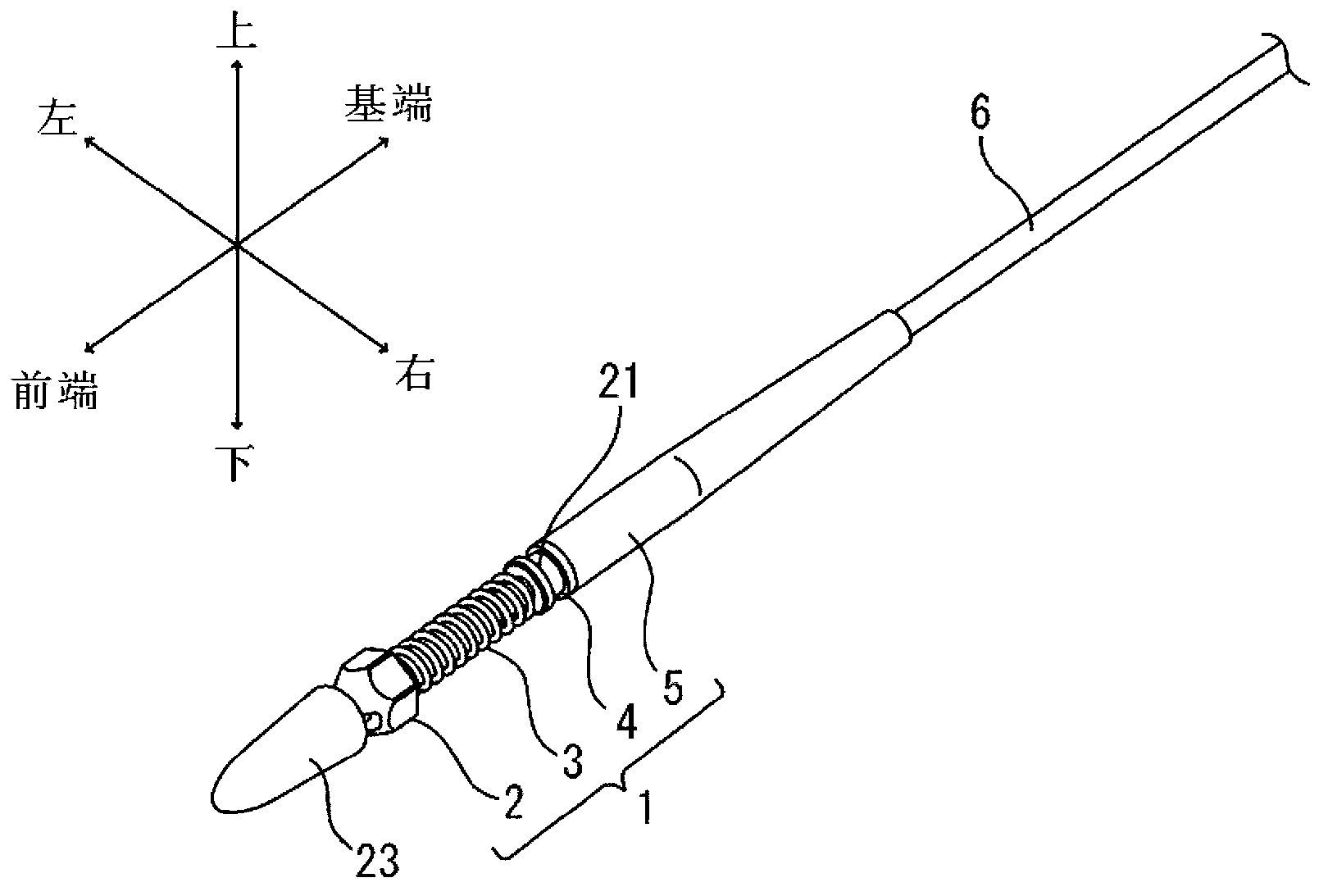
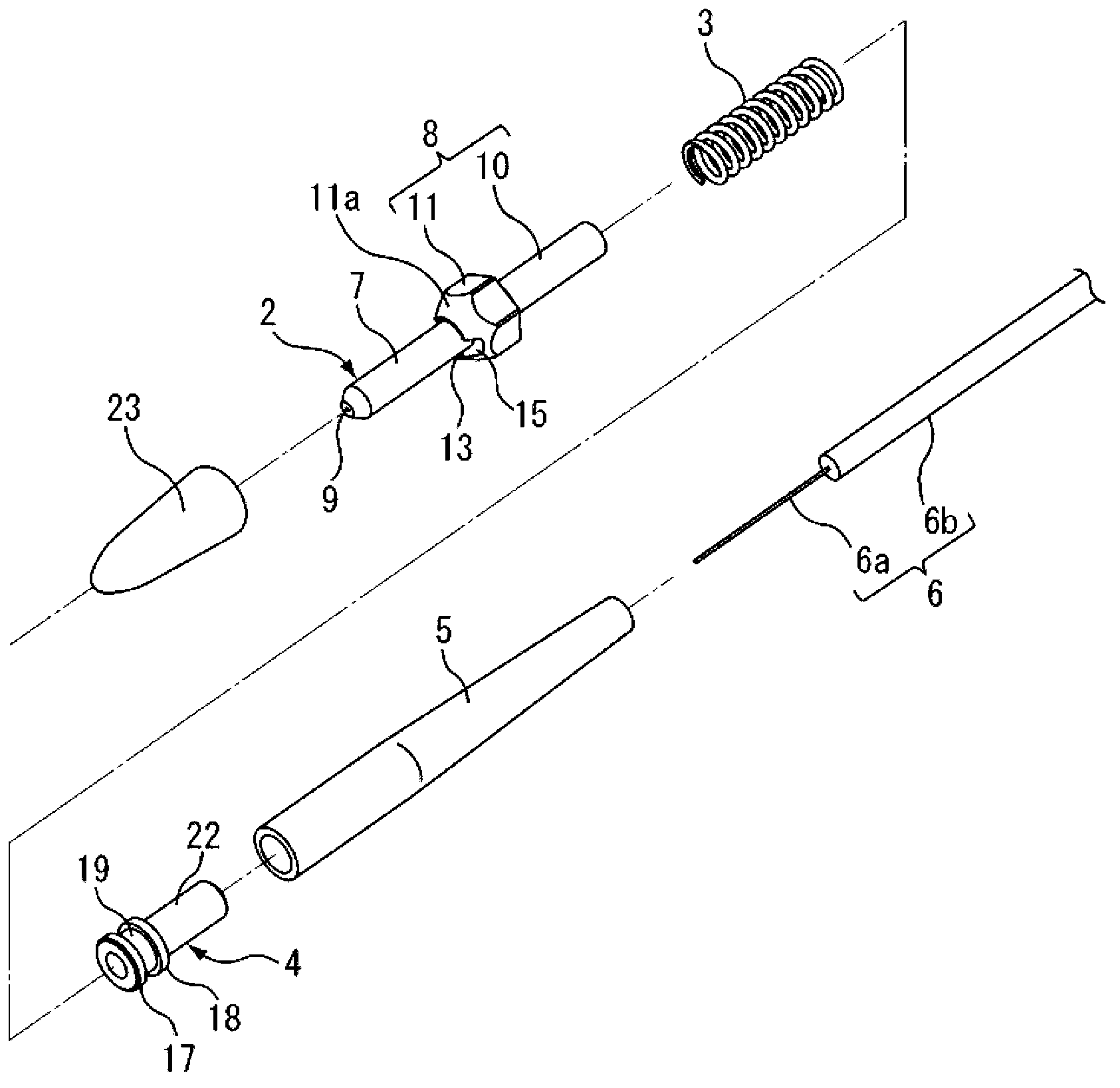
[0097] Installation of fiber optic connector components:

[0098] In this example, an optical fiber having a diameter of 0.9 mm and a length of 200 m was prepared. Next, the boot 5, snap ring 4 and coil spring 3 are sequentially inserted from the front end of the optical fiber 6, and after insertion, the coating material at the front end of the optical fiber 6 is removed to expose the optical fiber core wire 6a. Next, the front end of the optical fiber 6 is inserted into and held in the ferrule 2 , and the cap 23 is attached to the front end of the ferrule main body 7 . In addition, the stop ring 4 in Example 1 uses a product with a rib plate at the front end, and the optical fiber 6 uses a product with no special processing on the surface of the cladding material.

[0099] (transportation test)

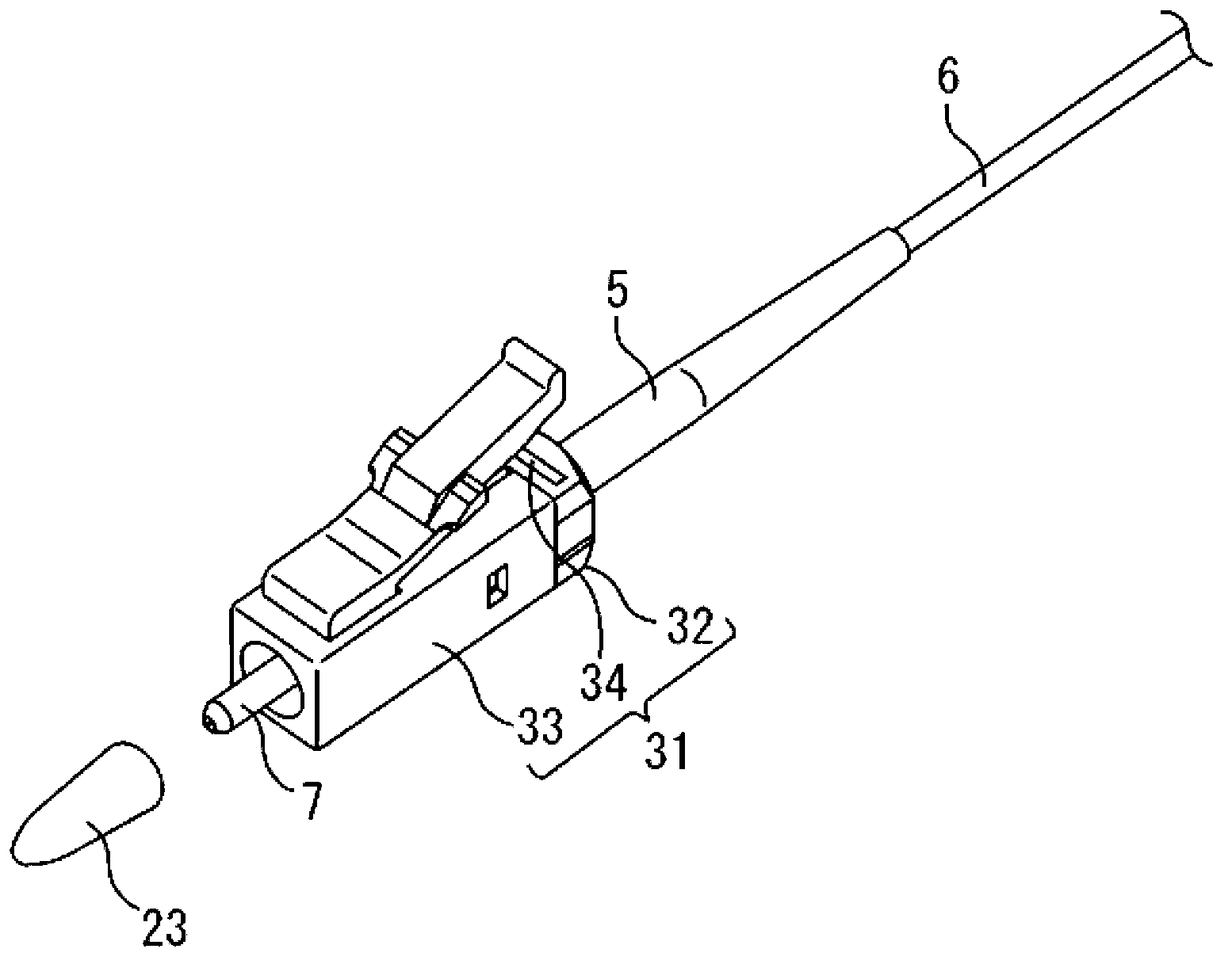
[0100] Next, a pay-off machine for discharging the optical fiber 6 is prepared, and the optical fiber 6 with the optical fiber connector component 1 attached to the tip is assemble...

Embodiment 2)

[0102] In the second embodiment, except that the boot 5 is not used, the optical fiber connector component 1 is installed on the optical fiber 6 in the same manner as the first embodiment. Next, a transport test was performed under the same conditions as in Example 1. The transport test results of Example 2 are shown in Table 1.


PUM


Abstract

Provided are an optical fiber connector component which holds an optical fiber and is capable of being inserted through a thin pipe and capable of being inserted smoothly through a pipe, and an optical fiber connector provided with the optical fiber connector component. The optical fiber connector component comprises a ferrule having a fiber hole to hold an inserted coaxially disposed optical fiber, a stop ring arranged on the base end side of the ferrule, and an urging means arranged in between the ferrule and the stop ring; the optical fiber connector is characterized by having a housing and cover member coaxially connected to the optical fiber, and the cover member being fixed to the stop ring of the optical fiber component by means of a fixing member.

Description

technical field [0001] The present invention relates to an optical fiber connector part and an optical fiber connector provided with the optical fiber connector part. Background technique [0002] Optical communication technology, which converts electrical signals into optical signals to transmit information, has the characteristics of being able to increase the communication speed and transmit large-capacity data compared with electrical communication. In recent years, these characteristics of optical communication technology have attracted people's attention. On newly constructed buildings, more and more pre-designs are carried out so that optical fibers can be laid during construction. In addition, laying optical fibers in existing buildings is also is increasing. [0003] Various wiring methods such as under-carpet wiring, open wiring, and concealed wiring are known as methods for wiring optical fibers. In recent years, from the viewpoint of maintaining a view even if ...

Claims


Application Information

Patent Timeline
Patent Type & Authority Applications(China)
IPC IPC(8): G02B6/36G02B6/46
CPCG02B6/3821G02B6/3849G02B6/3869G02B6/3871G02B6/54G02B6/38875G02B6/475G02B6/36G02B6/3624G02B6/38
Inventor 山内勲百武康弘狩野悟史
Owner NAMIKI PRECISION JEWEL CO LTD
Why Eureka
Try Eureka