Manufacturing method and manufacturing system for optical film laminates, and optical film laminate

An optical film and manufacturing method technology, applied in chemical instruments and methods, optics, optical components, etc., can solve the problems of liquid crystal display element defects, heightening, exposure, etc., and achieve the effect of preventing defects

Inactive Publication Date: 2013-07-03
NITTO DENKO CORP
View PDF5 Cites 8 Cited by
  • Summary
  • Abstract
  • Description
  • Claims
  • Application Information

AI Technical Summary

Problems solved by technology

[0003] However, in the above-mentioned method, when pasting a plurality of films, there is a problem that it is difficult to accurately align the widthwise ends of each film due to wrinkles of these films, etc.
In particular, when a plurality of films are formed with a width corresponding to the width of the liquid crystal panel, since the positions of the films in the width direction are rela

Method used


Image

  • Manufacturing method and manufacturing system for optical film laminates, and optical film laminate
  • Manufacturing method and manufacturing system for optical film laminates, and optical film laminate
  • Manufacturing method and manufacturing system for optical film laminates, and optical film laminate

Examples


Embodiment 1)

[0089] In Example 1, with Figure 3A The optical film laminated body 30 is formed by laminating the second film 32 and the third film 33 on the first film 31 according to the mode of . The width of the second film 32 is 398.6 mm, which is smaller than that of the first film 31 . The width of the third film 33 is 397.2 mm, which is smaller than that of the second film 32 . In this case, the protruding amount of the adhesive layer 32A of the second film 32 relative to the first film 31 and the protruding amount of the adhesive layer 33A of the third film 33 relative to the second film 32 are 0 mm, and the defect occurrence rate is 0. %.

Embodiment 2)

[0091] In Example 2, with Figure 3B The optical film laminated body 30 is formed by laminating the second film 32 and the third film 33 on the first film 31 according to the mode of . The width of the second film 32 is 397.3 mm, which is smaller than that of the first film 31 . The width of the third film 33 is 398.6 mm, which is larger than the width of the second film 32 and smaller than the width of the first film 31 . In this case, the adhesive layer 32A of the second film 32 does not protrude from the first film 31 , but the protruding amount of the adhesive layer 33A of the third film 33 from the second film 32 is 1 mm, and the defect occurrence rate is 1%.


PUM


Abstract

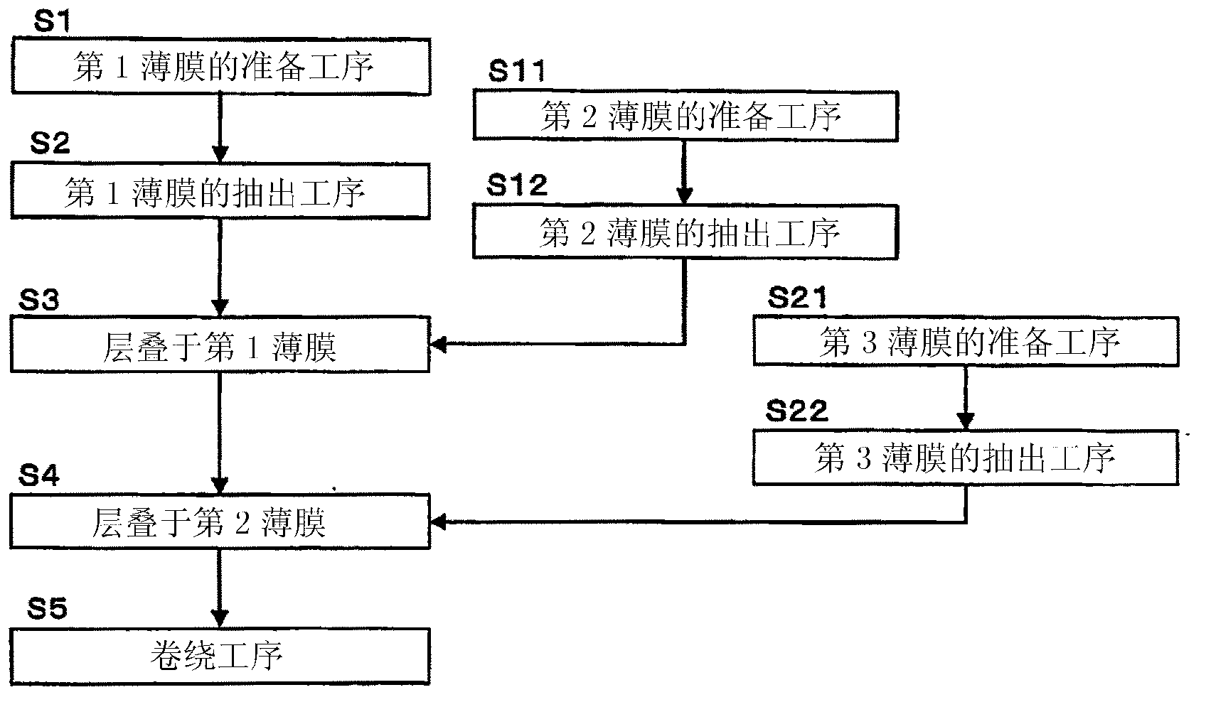
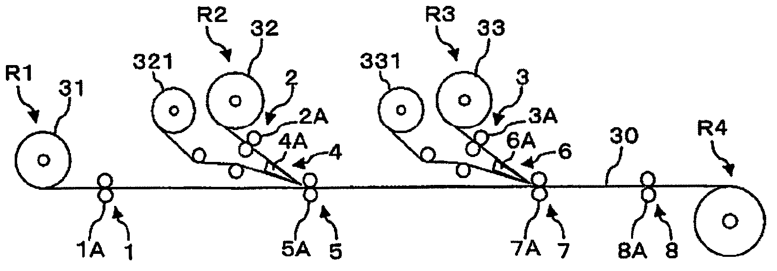
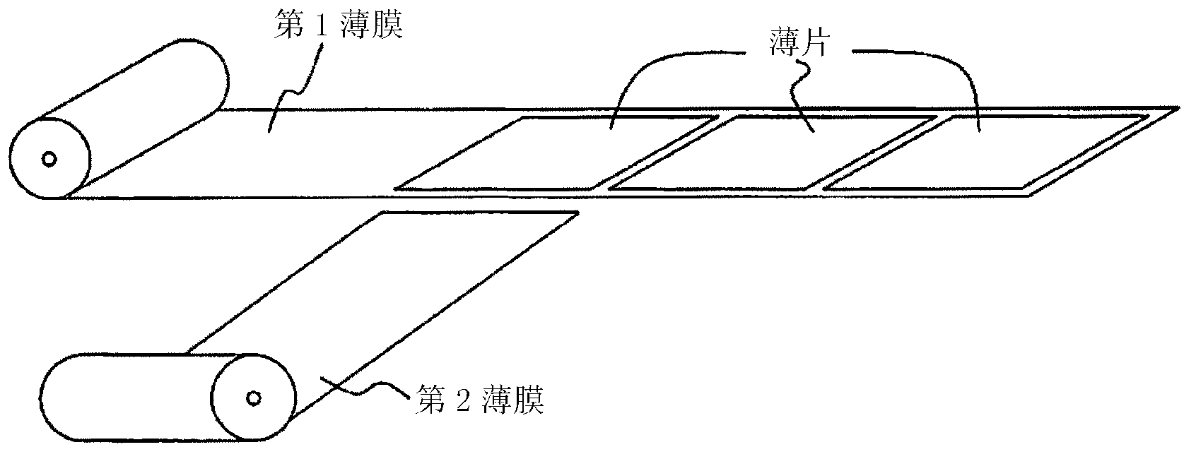
Provided is an optical film laminate wherein pressure-sensitive adhesive layers are not exposed to the outside. In a method for manufacturing said optical film laminate, the widths of a second film (32) and third film (33) which are laminated onto a first film (31) are both made smaller than the width of the first film (31), and the second film (32) and third film (33) are sequentially laminated onto the first film (31) such that neither protrudes past the first film (31) in the width direction. Thus, pressure-sensitive adhesive layers (32A and 33A) in the optical film laminate (30) are not exposed to the outside.

Description

technical field [0001] The present invention relates to a method for producing an optical film laminate comprising a plurality of films by sequentially laminating other films having the above-mentioned adhesive layer formed on one surface thereof on a first film via an adhesive layer and A manufacturing system, and an optical film laminate. Background technique [0002] A method of manufacturing a liquid crystal display element by bonding a plurality of films through an adhesive layer to form an optical film laminate, transporting the formed optical film laminate, and pasting the optical film laminate to a liquid crystal panel has been proposed. (For example, refer to Patent Documents 1 and 2). [0003] However, in the above-mentioned method, when sticking a plurality of films, there is a problem that it is difficult to align and stick both ends of the width direction of each film accurately due to wrinkles of these films. In particular, when a plurality of films are forme...

Claims


Application Information

Patent Timeline
IPC IPC(8): G02F1/1335B32B37/16G02B5/30
CPCB29D11/0073B29D11/00788B32B37/02B32B37/12B32B2307/40B32B2457/202G02B5/3033B32B37/16G02B5/30G02F1/1335
Inventor 平田聪近藤诚司宫武稔中园拓矢秦和也
Owner NITTO DENKO CORP
Why Eureka
Try Eureka