
Composite sand core sand shooting device and method

A technology of composite sand core and sand-shooting plate, applied in the direction of core, casting molding equipment, casting mold, etc., can solve the problems of multi-distribution, casting difficulty, irregularity, etc., achieve a wide range of applications, save costs, and reduce waste. Effect

Active Publication Date: 2013-07-10
GUANGXI YUCHAI MASCH CO LTD
View PDF9 Cites 7 Cited by
  • Summary
  • Abstract
  • Description
  • Claims
  • Application Information

AI Technical Summary

Problems solved by technology

However, the structure of the engine cylinder head is complicated, and there are many thin-walled positions and sharp corner positions in the middle part and the distribution is irregular. If the special positions that need to use high-strength sand materials are separated from the ordinary positions, and sand cores are made separately, then The sand core in a special position is difficult to fix in the sand box or casting mold, which makes casting more difficult
This makes it necessary to use expensive high-strength sand materials to manufacture integrated sand cores containing both special and common positions during actual production, which is very unfavorable for the control of production costs

Method used


Image

  • Composite sand core sand shooting device and method
  • Composite sand core sand shooting device and method
  • Composite sand core sand shooting device and method

Examples


Embodiment 1

[0032] Embodiment one: device embodiment

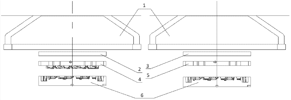
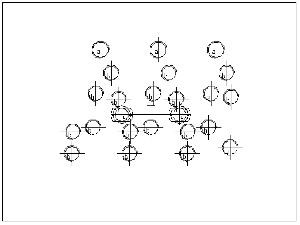
[0033] A composite sand core sand shooting device used for manufacturing sand cores in the cylinder head water jacket casting process on the engine cylinder head, such as figure 1 As shown, it includes a cold core shooting machine (not shown) with two sand shooting stations, a lower core box 6 and two upper core boxes with sand shooting holes, one of which is a special sand upper core box 4 , which is covered with a special sand shot board 2; the other is a common sand core box 5, covered with a common sand shot board 3. The cavity of the special sand upper core box 4 corresponds to the middle part of the lower core box 6, and there are many complicated raised structures on it, and these raised structures extend into the lower core box 6 to form the cavity of the middle part of the sand core. Corresponding to these raised structures, there are many sand shooting holes on the core box 4 on the special sand, such as Figure 4 shown. ...

Embodiment 2

[0036] Embodiment two: method embodiment

[0037] A composite sand core shooting method, such as Image 6 shown, including the following steps:

[0038] 1) Sand mixing step: use a double-station cold core shooting machine to mix special sand materials and ordinary sand materials with additives, and stir them evenly to form ordinary sand and special sand required for core making;

[0039]2) Special sand core shooting step: move the lower core box to the first station where special sand is applied, press the upper core box that needs to use special sand with the lower core box, and press the sand shooting plate corresponding to the upper core box Cover the upper core box to limit the range of sand shooting, use a cold core shooting machine to blow special sand into the core box and keep it for a period of time, and separate the core box after the sand core is solidified;

[0040] 3) Ordinary sand core shooting step: move the lower core box to the second station where ordinary ...


PUM


Abstract

The invention discloses a composite sand core sand shooting device comprising a lower core box and upper core boxes provided with sand shooting holes. The upper core boxes are at least two independent upper core boxes, wherein the mold cavity of each upper core box respectively corresponds to different positions of the lower core box. Preferably, the number of the upper core boxes is 2, wherein one upper core box has a mold cavity corresponding to the middle part of the mold cavity of the lower core box, and the other upper core box has a mold cavity corresponding to the peripheral part of the mold cavity of the lower core box. The position where the upper core box corresponds to the middle part of the mold cavity of the lower core box is a hollow cavity. One of the purposes of the invention is to provide a composite sand core sand shooting device used in cold core manufacturing, and another purpose of the invention is to provide a composite sand core sand shooting method used in composite sand core sand shooting. Therefore, a sand core, with which sand core strength can be ensured and cost can be effectively saved, can be manufactured.

Description

technical field [0001] The invention relates to a sand core shooting device and method, in particular to a composite sand core sand shooting device and method for cold core manufacturing process. Background technique [0002] When casting some parts with complex cavities, sand cores are needed. A relatively common sand core manufacturing process is to mix the sand material and additives (such as curing agent, adhesive, etc.) evenly, and then blow the mixed sand into the core box with compressed air, and wait for the sand to solidify. Sand cores will be formed. Sand cores made by this process are often called cold cores. [0003] For large parts such as the cylinder head water jacket of the engine cylinder block, due to its complex structure and high precision requirements, there are many special positions that are not conducive to casting, such as thin-walled structures and sharp-edged structures. The sand cores in these positions are in During the casting process, it has...

Claims


Application Information

Patent Timeline
IPC IPC(8): B22C15/23B22C9/10
Inventor 陈祖礼林振丽龙善北廖文东刘毅俸文斌张浩杨双华廉振文何春华
Owner GUANGXI YUCHAI MASCH CO LTD
Learn More