
Multifunctional steering wheel mechanism for electric automobile

A multi-functional steering wheel and electric vehicle technology, which is applied to the steering control, vehicle parts, anti-theft vehicle accessories and other directions installed on the car, can solve the problems of structural defects of the steering wheel, inconvenient maintenance, and difficulty in entering the cab, and achieve Elimination of process and cost, car safety, and cost-saving effects

Active Publication Date: 2013-07-10
福建艾密克新能源科技有限公司
View PDF5 Cites 2 Cited by
  • Summary
  • Abstract
  • Description
  • Claims
  • Application Information

AI Technical Summary

Problems solved by technology

Due to the difference in human body size, when the driver enters the cab, for example, the previous driver is smaller and his seat is adjusted too far forward, while the driver who enters later has a larger body size, which will cause him to enter the cab. It is very difficult; in addition, some short drivers have difficulty stepping on the clutch and accelerator pedal, so they have to adjust the seat very forward, so that the steering wheel rests on the chest, which affects the operability when driving
Therefore, due to the structural defects of the steering wheel, it cannot be well adapted to the operation of drivers of all sizes
Secondly, although the structure of the traditional safety steering wheel is not complicated, once it is broken, its maintenance is very inconvenient
Finally, the existing car steering wheel does not have an anti-theft function, and can only be realized by additional auxiliary devices, for example, adding a car steering wheel lock on the steering wheel to realize
To sum up, the existing safety steering wheel has a single function, which is difficult to meet modern people's pursuit of high-quality cars.

Method used


Image

  • Multifunctional steering wheel mechanism for electric automobile
  • Multifunctional steering wheel mechanism for electric automobile
  • Multifunctional steering wheel mechanism for electric automobile

Examples


Embodiment Construction

[0019] A detailed description will be made below in conjunction with the accompanying drawings.

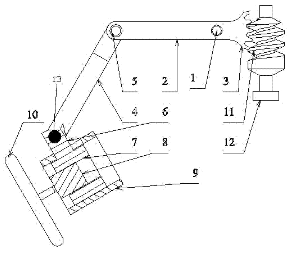
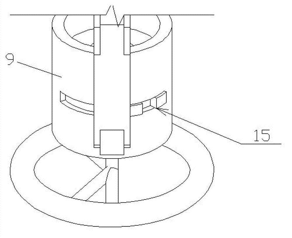
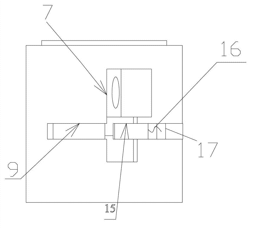
[0020] see Figure 1-5 , the steering wheel 10 is fixedly connected to the steering column 8, and the outer wall of the steering column 8 is fixedly connected to the inner ring of the bearing 7. The bearing 7 is built in a sleeve 9, and the outer ring of the bearing 7 forms a connecting lug 6, which protrudes out of it through a guide groove on the sleeve 9, and the connecting lug 6 can drive the bearing 7 in the sleeve 9 The inner axis moves, and the fixed sleeve 9 is installed on the vehicle body.

[0021] The outer end of connecting ear 6 and an end of rocking bar 4 are hinged by connecting pin 13, and when steering wheel is subjected to heavy pressure, this connecting pin 13 is pressed off, to realize the function of safety disc. The other end of rocking bar 4 is hinged with an end of crank 2 by connecting pin 5, and the other end of crank 2 has a locating hole, and this loc...


PUM


Abstract

The invention discloses a multifunctional steering wheel mechanism for an electric automobile. The multifunctional steering wheel mechanism comprises a steering wheel, the steering wheel is fixedly connected with a steering wheel column, an outer wall of the steering wheel column is fixed with an inner ring of a bearing, the bearing is arranged in a sleeve and is axially slidably matched inside the sleeve, an outer ring of the bearing forms a connecting lug, and the connecting lug extends out of the sleeve through a guide groove axially arranged on the sleeve. The outer end of the connecting lug is hinged to one end of a rocking rod through a first connecting pin, the other end of the rocking rod is hinged to one end of a crank through a second connecting pin, the other end of the crank is assembled on an automobile body in a swinging mode through a pin, teeth are formed at the end of the crank and are meshed with a worm, and the worm is driven by a stepping motor. When an automobile is shut down or drivers start the automobile, a telescopic function of the steering wheel is achieved through an electric control switch, and the drivers of any body type can freely enter a cab and can adjust the position of the steering wheel according to their requirements.

Description

technical field [0001] The invention belongs to the technical field of electric vehicle manufacturing, and in particular relates to a multifunctional steering wheel capable of realizing vehicle anti-theft, automatic expansion and contraction, and the like. Background technique [0002] In order to solve the damage of the steering wheel to the driver when the car collides, researchers at home and abroad have designed a safe steering wheel, which is connected by pins in the middle of two shafts. When the car is hit by a collision, people are pressed on the steering wheel due to inertia , Give the lock pin a shear force through the steering wheel to break it, and the steering wheel shrinks downwards, thereby cushioning the human body, reducing the impact force, and enhancing safety performance. However, it has the following drawbacks. First, in normal use, its drive shaft is fixed. Due to the difference in human body size, when the driver enters the cab, for example, the prev...

Claims


Application Information

Patent Timeline
IPC IPC(8): B62D1/11B60R25/0215
Inventor 孟庆华黄琴宝
Owner 福建艾密克新能源科技有限公司
Learn More