Drainage system of solid waste disposal site

A solid waste and drainage system technology, applied in protection devices, buildings, infrastructure projects, etc., can solve the problems of increasing the risk of flooding in the disposal unit 12, increasing the risk of nuclide release and migration, and large investment, reducing The effect of maintaining workload and personnel exposure dose, improving long-term natural safety, and reducing project cost

Active Publication Date: 2013-07-10
中广核工程有限公司 +1
View PDF10 Cites 2 Cited by
  • Summary
  • Abstract
  • Description
  • Claims
  • Application Information

AI Technical Summary

Problems solved by technology

[0007] However, it takes about 300 to 500 years for the low- and medium-level radioactive waste disposed of in the disposal site to decay to the level of clean release, while reinforced concrete engineering barriers usually only have a validity period of about 100 years.
In the above-mentioned drainage system, the drainage pipe gallery 20 is set directly below the disposal unit 12, and the drainage pipe gallery 20 is about 2m high and 1.2m wide; after the disposal unit 12 is covered, the upper part of the disposal unit 12 will also bear about The covering layer 14 is composed of different materials with a thickness of 5m. Therefore, the drainage pipe gallery 20 itself bears a relatively high structural strength. After hundreds of years of operation, it is likely that the reinforced concrete will fail to bear the weight of the disposal unit 12 and the covering layer 14. And then cause the drainage pipe gallery 20 to collapse
The collapse of the drainage pipe gallery 20 will cause the settlement of the disposal unit 12, and the covering layer 14 will form cracks between different layers due to the settlement of the disposal unit 12, so that the water blocking effect will be weakened and the risk of the disposal unit 12 being flooded will be further increased; On the other hand, the collapse of the drainage pipe gallery 20 will damage the dialysis water collection system, making it impossible to discharge the dialysis water in the disposal unit 12, and further increase the soaking time of the waste barrel 10 in the disposal unit 12, increasing the The risk of nuclide release and migration
[0008] In addition, to set up the drainage pipe gallery 20 at the bottom of the disposal unit 12, the drainage pipe gallery 20 needs to be built at one time, which requires a large amount of work and a large investment; however, due to the amount of waste generated, the disposal unit 12 is usually built in batches , this will also cause the drainage system of the disposal unit 12 to be unused for a long time, and the maintenance workload will be heavy
And because the drainage pipe gallery 20 is built at the bottom of the disposal unit 12, due to the relationship between the structural load and the failure of the structure, the pipe gallery 20 itself cannot ensure the safety of the disposal unit 12 for a long time within 300 to 500 years. After the partial collapse of the gallery 20, the newly built pipe gallery 20 and the original pipe gallery 20 need to be connected and the structural load bearing must be taken into consideration. Coupled with the risk of radioactive leakage, it is difficult to repair the drainage pipe gallery 20

Method used


Image

  • Drainage system of solid waste disposal site
  • Drainage system of solid waste disposal site
  • Drainage system of solid waste disposal site

Examples


Embodiment Construction

[0031] In order to make the purpose of the invention, technical solution and beneficial technical effects of the present invention clearer, the present invention will be further described in detail below in conjunction with the accompanying drawings and specific implementation methods. It should be understood that the specific implementations described in this specification are only for explaining the present invention, not for limiting the present invention.

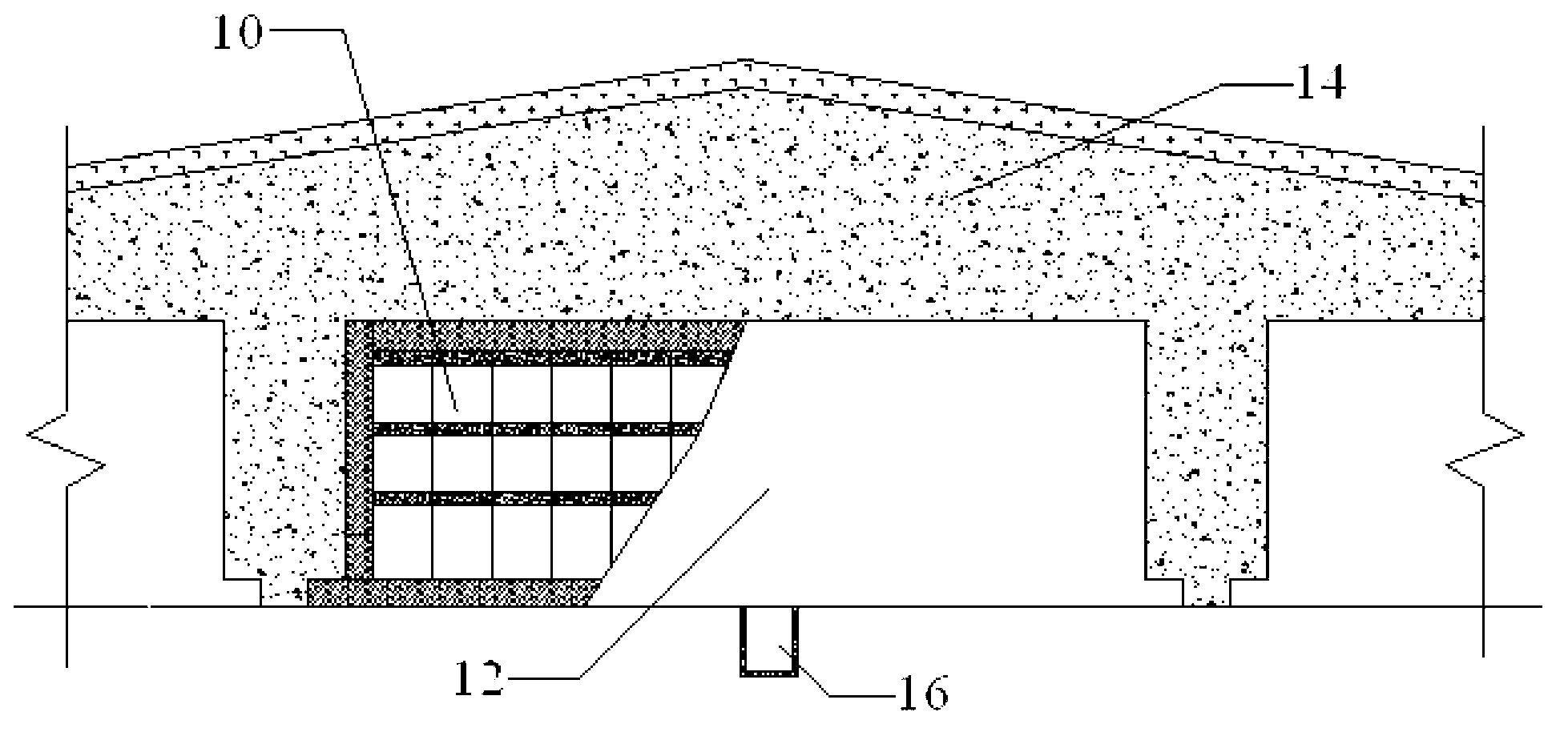
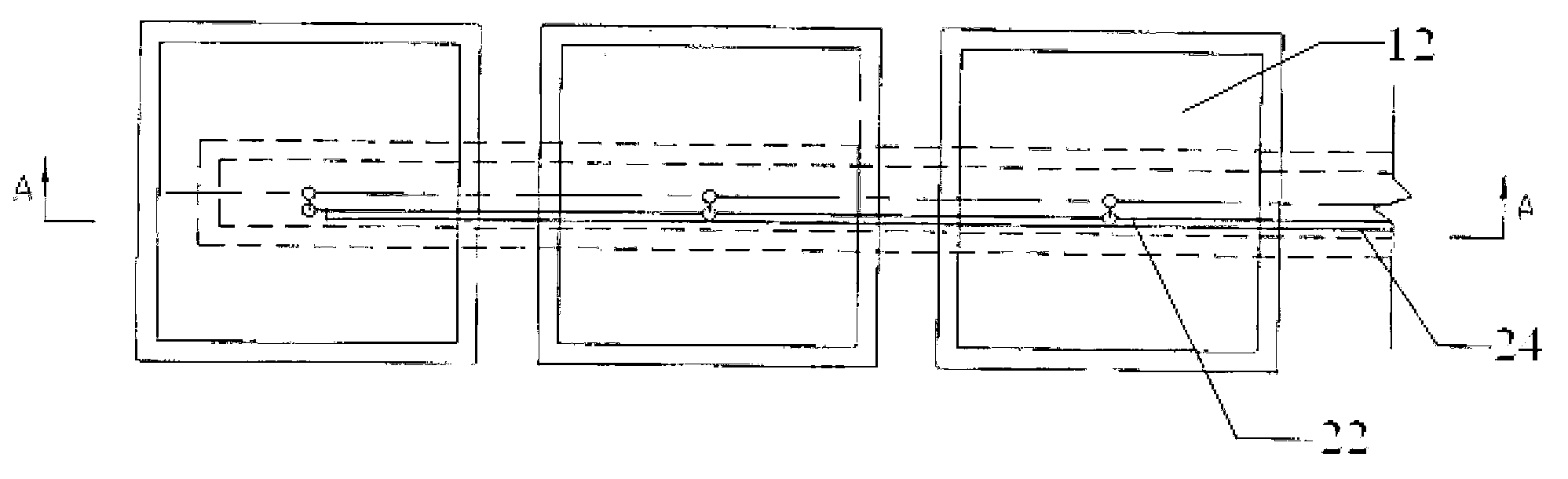
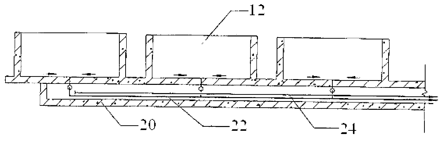
[0032] The first embodiment of the drainage system of the solid waste disposal site of the present invention is a pipe gallery scheme, which includes a disposal unit, a dialysis water collection system, and a dialysis water collection and treatment plant.

[0033] see Figure 4 , the bottom plate 32 of the handling unit includes two opposite first sides 320 , one second side 322 and one third side 324 opposite to the second side 322 . The bottom plate 32 is provided with a downward slope of 1% from the two first sides ...


PUM


Abstract

The invention discloses a drainage system of a solid waste disposal site. The drainage system comprises disposal cells with dialysis water holes, a dialysis water collecting system and dialysis water collecting disposal plant. Each dialysis water hole is reserved at a side edge of a base plate of each disposal cell. The dialysis water collecting system is disposed under the ground of the side of each row of disposal cells. Compared with the prior art, due to the drainage system is disposed under the ground of the sides of the disposal cells, the drainage system does not fail due to large load bearing and is higher in stability, sedimentation, caused by failure of engineering barriers, of disposal cells is avoided, the disposal cells and covering layers are protected, natural safety of the disposal site is improved, maintenance work load of the drainage system and exposure dose of staff are lowered, work amount reduction is facilitated, and project cost is lowered.

Description

technical field [0001] The invention belongs to the field of low and medium radioactive solid waste disposal, and more specifically relates to a unit cell dialysis water drainage system for low and medium radioactive solid waste disposal sites. Background technique [0002] Low- and medium-level radioactive solid waste generated by nuclear power plants and nuclear technology utilization generally adopts near-surface disposal schemes. According to the relative elevations of the floor of the disposal unit and the disposal site during construction and operation, the near-surface disposal methods for low- and intermediate-level solid waste commonly used in the world can generally be divided into three methods: above-ground, underground and semi-underground. [0003] see figure 1 , in the above-ground disposal method, the waste drums 10 containing low- and medium-level radioactive solid waste are stacked in the disposal unit 12 according to the set stacking method, and the gaps ...

Claims


Application Information

Patent Timeline
Patent Type & Authority Applications(China)
IPC IPC(8): E02D31/00
Inventor 李超潘跃龙邓先宽
Owner 中广核工程有限公司
Why Eureka
Try Eureka