Reciprocating impact tunnel boring machine

A technology of percussion drill and excavator, applied in the field of mine excavation equipment

Active Publication Date: 2013-07-10
刘素华
View PDF8 Cites 10 Cited by
  • Summary
  • Abstract
  • Description
  • Claims
  • Application Information

AI Technical Summary

Problems solved by technology

Its defect is that the coal shearer only performs reciprocating impact and does not perform drilling and excavation functions.

Method used


Image

  • Reciprocating impact tunnel boring machine
  • Reciprocating impact tunnel boring machine
  • Reciprocating impact tunnel boring machine

Examples


Embodiment 1

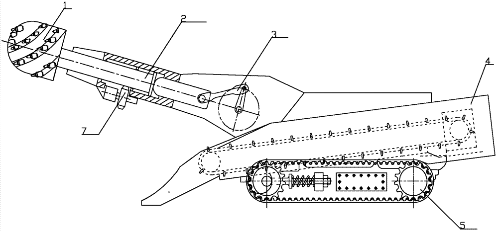
[0049] figure 1 and figure 2 It is the reciprocating impact drilling machine described in Embodiment 1. The drilling machine includes a fuselage 4 , and the fuselage 4 includes a traveling mechanism 5 and an impact rotary drilling mechanism 2 , wherein the traveling mechanism 5 is arranged at the bottom of the fuselage 4 . The impact rotary drilling mechanism 2 includes an impact device 3, a rotary drilling device 7 and a drill bit 1, the rotary drilling device 7 is slidingly connected with the drill bit 1, and the rotary drilling device 7 drives the drill bit 1 to rotate. Simultaneously, the impact device 3 impacts the drill bit 1, and the impact device 3 is driven in cooperation with the rotary drilling device 7 to make the drill bit 1 impact and rotate. The traveling mechanism 5 drives the body 4 to walk, and the body 4 walks to drive the impact rotary drill 2 to walk. Fuselage travel makes 3 block back drill bit 1 through rock wall, makes drill bit realize rotary drill...

Embodiment 2

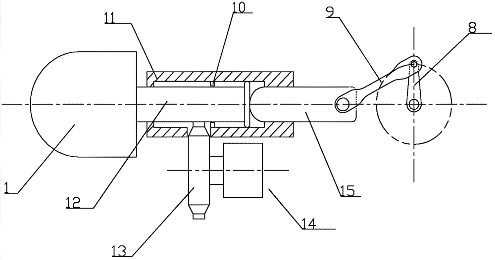
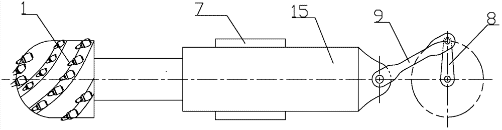
[0054] image 3 and Figure 4 It is the reciprocating impact drilling machine described in Embodiment 2. In this embodiment, the rotary drilling device 7 includes a spline column rotary drilling device. The impact device includes an impact power component 8, a connecting rod 9 and an impactor 15. One end of the connecting rod 9 is connected to the impact power component 8, and the other end Connect with impactor 15. The impact power part 8 drives the connecting rod 9 to reciprocate, and the connecting rod 9 drives the impactor 15 to impact. The front end of the spline column rotary drilling device is provided with a spline sleeve bit corresponding to the spline column rotary drilling device, and the spline column rotary drilling device is arranged on the impactor 15, and the impactor 15 drives the spline column rotary drilling device and the spline The drill bit reciprocates and impacts, the spline column rotary drilling device drives the drill bit to rotate, the drill bit ...

Embodiment 3

[0058] Figure 5 It is the reciprocating impact drilling machine described in embodiment 3. In this embodiment, the rotary drilling device includes a spline column rotary drilling device, the spline column rotary drilling device is arranged on the fuselage, the impact device includes an impact power part 8, a connecting rod 9 and an impactor 15, and the impact power part 8 Set on the fuselage, the impact power part 8 drives the connecting rod 9 to reciprocate, and the connecting rod 9 drives the impactor 15 to impact. The spline column rotary drilling device includes a spline column 18 and a rotary drilling power component 17. The spline column rotary drilling device The front end of the spline sleeve is provided with a spline sleeve bit corresponding to the spline column rotary drilling device, and the rear portion of the spline sleeve drill bit is provided with a spline sleeve 19 corresponding to the spline column. The spline sleeve 19 is a cavity structure, and the spline s...


PUM


Abstract

The invention relates to mine excavation equipment, and in particular to a reciprocating impact tunnel boring machine. The machine comprises a machine body with a walking mechanism; the reciprocating impact tunnel boring machine also comprises an impact rotary drilling mechanism comprising an impact device, a rotary drilling device and a drill; the rotary drilling device is slidably connected with the drill; the rotary drilling device drives the drill to rotate; the impact device impacts the drill; the drill rotates for impact; the impact device cooperates with the rotary drilling device to drive the drill for impact rotation; the impact rotary drilling mechanism is arranged on the machine body; the walking mechanism drives the machine body for walking; the machine body walks to block back the drill through the rock; and the drill rotates for reciprocating impact. The reciprocating impact tunnel boring machine changes an excavation way only conducting drilling without reciprocating impact of an original boring machine, and a cutting part drills while reciprocating for impact, so as to improve driving efficiency, greatly improve drilling efficiency, optimize boring working environment, and greatly reduce energy consumption of the mining machine.

Description

technical field [0001] The invention relates to a mine excavation equipment, in particular to a reciprocating impact drilling machine. Background technique [0002] The currently widely used mining excavation equipment is mainly the cantilever type roadheader. Its working principle is drilling tunneling, which determines that the grinding and crushing of this tunneling method is relatively large, especially in the state of compressive stress, which consumes a lot of energy and reduces the productivity of tunneling. The advancement of the drill bit is completed by the walking of the fuselage , in order to make the drill bit drill quickly, the thrust of the machine body to speed up the progress of the excavation continues to increase, causing greater damage to the machine body. [0003] The patent number is 200620137402.7, and the name is "small energy-saving impact coal shearer" which discloses a coal shearer with an impact arm and an impact head. The output of the motor is...

Claims


Application Information

Patent Timeline
Patent Type & Authority Applications(China)
IPC IPC(8): E21C27/20
Inventor 刘素华
Owner 刘素华
Why Eureka
Try Eureka