
Device and method of engine, based on cam and with variable oil supply correct time and duration

An engine and duration technology, which is applied to engine components, machines/engines, fuel injection devices, etc., can solve problems such as increased engine cost, decreased reliability, and gear damage, and achieves the goals of reducing emissions, improving power and economy Effect

Active Publication Date: 2013-07-10
TIANJIN UNIV
View PDF9 Cites 10 Cited by
  • Summary
  • Abstract
  • Description
  • Claims
  • Application Information

AI Technical Summary

Problems solved by technology

As shown in the patent application No. 201210285956.1, the plunger sleeve is driven by the advance angle adjustment gear and can move up and down, so as to realize the independent adjustment of the oil supply amount and the oil supply advance angle. However, it can also be seen that due to the oil in the plunger sleeve The pressure is very high. If the adjustment gear is only used to drive up and down, the gear will bear too much pressure. If it is light, the gear will shift and the adjustment will not be accurate. If it is heavy, the gear will be damaged.
[0004] For example, in the hydraulic variable valve system, we need to control the opening duration and opening time of the valve, which generally requires a high-response solenoid valve for control, which increases the cost of the engine and reduces the reliability. Therefore, if it can The development of a hydraulic variable valve system without solenoid valve control and meeting the demand has always been the expectation of people.

Method used


Image

  • Device and method of engine, based on cam and with variable oil supply correct time and duration
  • Device and method of engine, based on cam and with variable oil supply correct time and duration
  • Device and method of engine, based on cam and with variable oil supply correct time and duration

Examples


Embodiment Construction

[0016] The present invention will be further described in detail below in combination with specific embodiments.

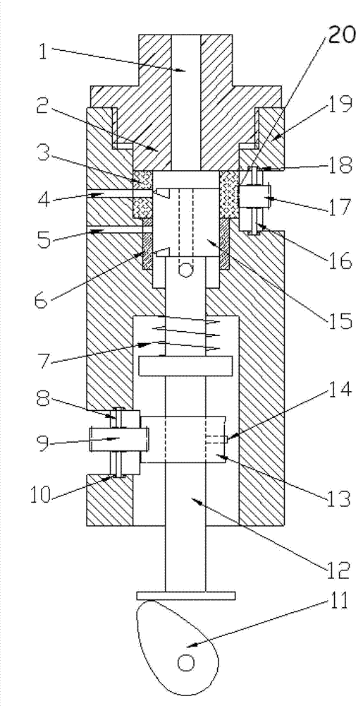
[0017] Such as figure 1 Shown is a cam-based engine variable oil supply timing and duration device of the present invention, including a pump body 19, a pump cover 2, a plunger 15, a plunger sleeve, a plunger spring 7, a push rod 12 and an engine cam 11.

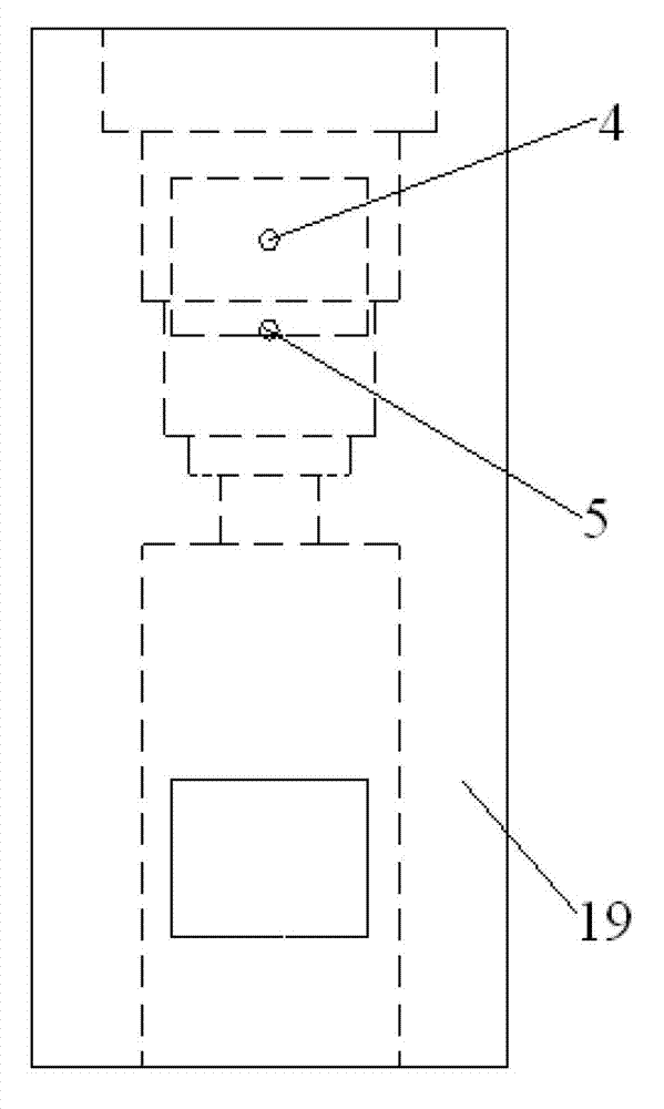
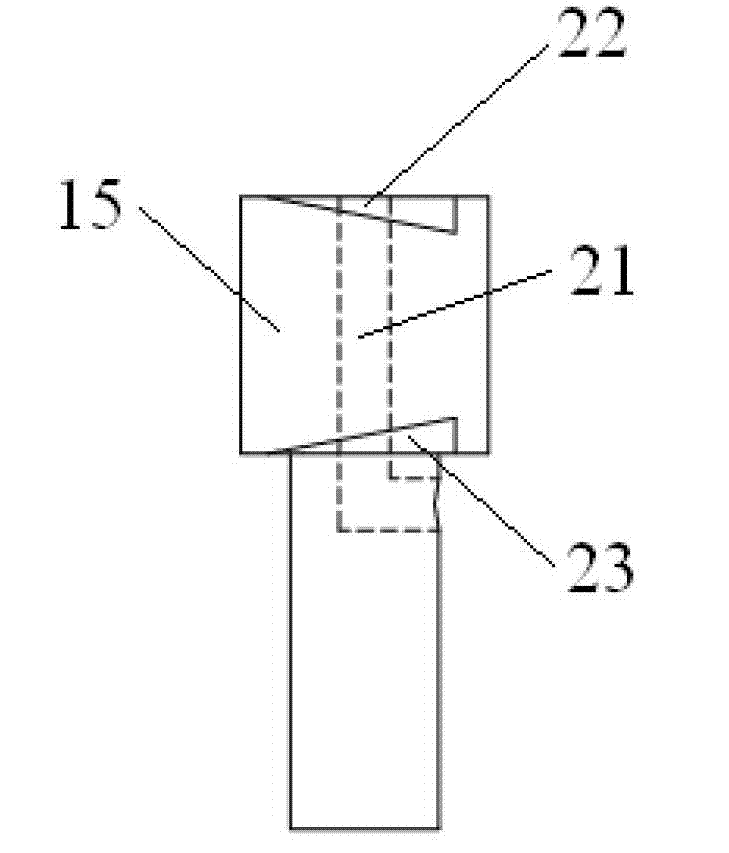
[0018] The plunger sleeve is slidingly fitted with the plunger 15, the plunger 15 is connected with the push rod 12, and the upper part of the pump body 19 is provided with a first oil inlet and outlet passage 4 and a second oil inlet and outlet passage 5 ( Such as figure 2 shown); the upper part of the pump body 19 is provided with a first control gear 17, and the lower part of the pump body 19 is provided with a second control gear 9; the plunger sleeve is composed of a plunger sleeve upper body 3 and a plunger sleeve The lower body 6 is formed. The upper body 3 of the plunger sleeve and the lower body 6 o...


PUM


Abstract

The invention discloses a device based on cam power and with variable oil supply correct time and duration. The device comprises a pump body, two oil feeding-returning channels arranged on the pump body, a pump cover, a plunger, a plunger sleeve, a plunger spring, two control gears, an engine cam, a gear with a pin slot, a pin, a control gear and an ejection rod. A group of outer gears meshed with one control gear are arranged on the outer rotating surface of the plunger sleeve, and the plunger sleeve can rotate independently relative to the pump body by rotating the control gear. The ejection rod connected with the plunger is driven by the gear with the pin slot to rotate through the pin, and the plunger can also rotate independently relative to the pump body under control of the other control gear. The device achieves single adjustment at oil supply correct time by adjusting relative position of the plunger and a plunger sleeve upper body in the axial direction and achieves single adjustment of oil quantity by adjusting synchronous rotating of the plunger sleeve upper body and the plunger. The device can achieve independent adjustment of oil supply time and oil supply quantity, reduces discharge and improves dynamic performance and economy of the engine.

Description

technical field [0001] The invention relates to an engine hydraulic actuator, in particular to a diesel fuel injection system and a hydraulic variable valve system. Background technique [0002] The internal combustion engine is still the prime mover with the highest thermal efficiency, the largest power per unit volume and unit weight, and is widely used. However, with the gradual shortage of energy in the world and the continuous deterioration of environmental resources, we need internal combustion engines to meet stricter emission regulations. Different control strategies are used in different working conditions of the engine. [0003] For example, in the fuel injection system, according to the load and speed, a certain amount of fuel needs to be injected at an appropriate engine advance angle. The fuel supply advance angle and the fuel supply amount of the traditional internal combustion engine fuel injection pump are interrelated and not separated independently. Those ...

Claims


Application Information

Patent Timeline
IPC IPC(8): F02M59/26F02M59/28
Inventor 尧命发张翔宇郑尊清李永志
Owner TIANJIN UNIV
Learn More