
Surface acoustic wave gyroscope based on traveling wave mode

A gyroscope and pattern technology, applied in gyroscope/steering sensing equipment, gyroscope effect for speed measurement, instruments and other directions, can solve the problems affecting the improvement of sensor accuracy, low detection sensitivity of gyroscope, difficult sensor temperature compensation, etc., to achieve improvement Lower detection limit and stability, improved detection sensitivity, improved Coriolis force

Inactive Publication Date: 2013-07-10
INST OF ACOUSTICS CHINESE ACAD OF SCI
View PDF3 Cites 15 Cited by
  • Summary
  • Abstract
  • Description
  • Claims
  • Application Information

AI Technical Summary

Problems solved by technology

However, this standing wave mode SAW gyroscope still has some obvious defects: the output signal is an electrical signal at the microvolt level, which affects the accuracy of the sensor; in addition, due to the use of LiNbO with high voltage characteristics 3 As a device substrate, its high temperature coefficient leads to the temperature instability of the sensor, and it is difficult to realize the temperature compensation of the sensor limited by the sensor cross structure
However, the SAW gyroscope 2 also faces some problems. Since the Coriolis force directly acts on the propagating sound wave, the mass of the vibrating particle is extremely small, resulting in a weak Coriolis force, which makes the detection sensitivity of the gyroscope extremely low, which is far from meeting the needs of practical applications.

Method used


Image

  • Surface acoustic wave gyroscope based on traveling wave mode
  • Surface acoustic wave gyroscope based on traveling wave mode
  • Surface acoustic wave gyroscope based on traveling wave mode

Examples


Embodiment Construction

[0055] For a more complete understanding of the invention, and to realize additional objects and advantages of the invention, a detailed description of the invention will now be made with reference to the accompanying drawings.

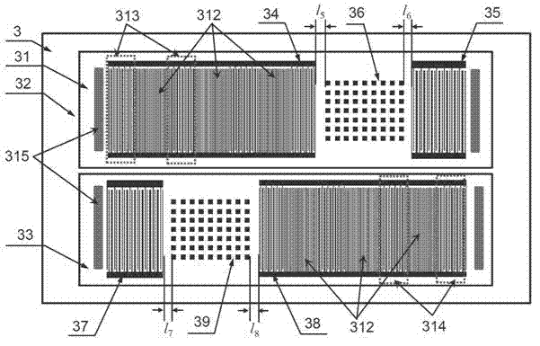
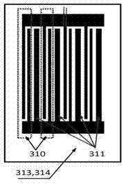
[0056] The SAW gyroscope of the novel traveling wave mode provided by the present invention includes: two groups of LiTaO gyroscopes arranged in the same 112° cut around Y and propagating along the X direction 3 The first SAW delay line 31 and the second delay line 33 using EWC / SPUDT and comb transducers on the piezoelectric substrate are arranged between the interdigital transducers of the first delay line 31 and the second delay line 33 The first metal dot matrix 36 and the second metal dot matrix 39, and the sound-absorbing glue arranged at both ends of the first delay line 31 and the second delay line 33, the specific structure is as follows image 3 shown.

[0057] The first delay line 31 and the second delay line 33 are fabricated on the same p...


PUM


Abstract

The invention relates to a surface acoustic wave (SAW) gyroscope based on a traveling wave mode. The SAW gyroscope (3) comprises a piezoelectric substrate (32), a first delay line (31) and a second delay line (33) arranged on the surface of the piezoelectric substrate (32), and sound-absorbing rubbers (35) distributed at both ends of the first delay line (31) and the second delay line (33). The SAW gyroscope is characterized in that a first metal lattice (36) is distributed between two interdigital transducers of the first delay line (31), and a second metal lattice (39) is distributed between two interdigital transducers of the second delay line (33), the first delay line (31) and the second delay line (33) are parallelly and reversely arranged and has a same structure. The piezoelectric substrate (32) is a LiTaO3 piezoelectric substrate rotating around a Y direction for 112 DEG and cut, and spreading along an X direction. Through the above structure, a detection sensitivity of the gyroscope is effectively improved.

Description

technical field [0001] The present invention relates to a surface acoustic wave gyroscope (hereinafter referred to as a SAW gyroscope) in acoustic technology, in particular to a surface acoustic wave gyroscope based on a traveling wave mode. Background technique [0002] Compared with other types of gyroscopes such as optical fiber, micromachines, and infrared gyroscopes, gyroscopes based on surface acoustic wave technology have the characteristics of simple structure, strong anti-vibration ability, long service life, and low cost (Lv Zhiqing et al., "MEMS-IDT Surface Acoustic Wave Gyroscope", Micro-Nano Electronics Technology, 40(4), 2003, 27-33). Prior art SAW gyroscopes have two modes. One is a SAW gyroscope based on a so-called standing wave mode (Varadan V.K, "Design and development of a MEMS-IDT gyroscope", Smart Mater. Struct., 2000, 9, pp.898-905; Kose et al, "Surface acoustic wave MEMS gyroscope”, Wave Motion, Vol.36, 2002, pp:367-381), such as figure 1 As shown,...

Claims


Application Information

Patent Timeline
Patent Type & Authority Applications(China)
IPC IPC(8): G01C19/5698
Inventor 王文邵秀婷何世堂
Owner INST OF ACOUSTICS CHINESE ACAD OF SCI
Learn More