Structural dynamic defective optical fiber microscopic monitoring device

A monitoring device and optical microscope technology, which is used in measuring devices, optical testing flaws/defects, instruments, etc., can solve the problems of defect fiber microscopic monitoring devices and measuring devices that cannot monitor the surface condition, and achieve high precision and ensure safety. Effect

Inactive Publication Date: 2013-07-10
HARBIN INST OF TECH
View PDF7 Cites 3 Cited by
  • Summary
  • Abstract
  • Description
  • Claims
  • Application Information

AI Technical Summary

Problems solved by technology

[0003] The purpose of the present invention is to solve the problem that the existing measuring device cannot monitor its surface state under the dynamic state of the structure, and provides a fiber optic microscopic monitoring device for structural dynamic defects

Method used


Image

  • Structural dynamic defective optical fiber microscopic monitoring device
  • Structural dynamic defective optical fiber microscopic monitoring device
  • Structural dynamic defective optical fiber microscopic monitoring device

Examples


specific Embodiment approach 1

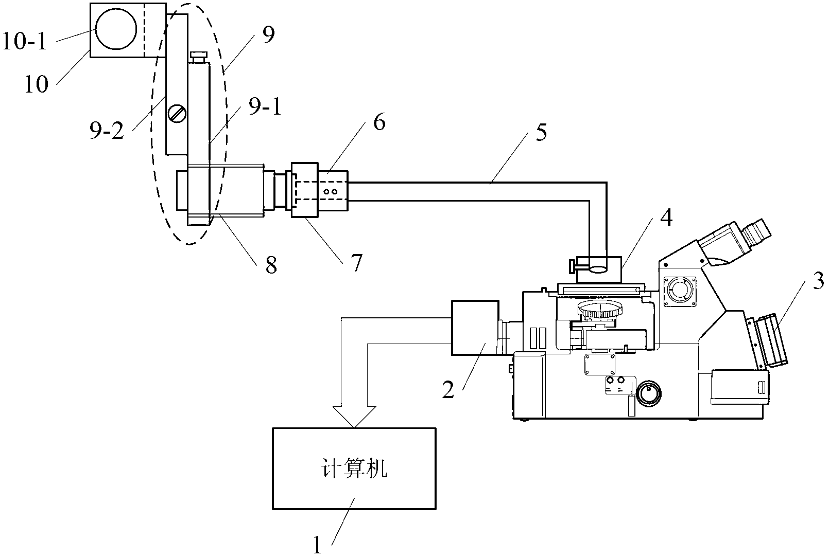
[0031] Specific implementation mode one: the following combination Figure 1 to Figure 3 Describe this embodiment mode, a fiber optic microscopic monitoring device for structural dynamic defects described in this embodiment mode, which includes: a computer 1, a CCD camera 2, an optical microscope 3, a fixed block 4, an optical fiber image transmission bundle 5, an adapter 6, a micro Microscope 7, threaded interface 8, two-dimensional fine-tuning system 9 and fixture 10;

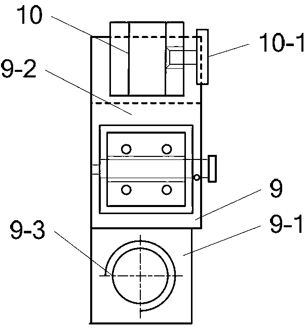
[0032] The two-dimensional fine-tuning system 9 includes a longitudinal adjustment mechanism 9-1 and a horizontal adjustment mechanism 9-2; and one end of the longitudinal adjustment mechanism 9-1 is provided with a connecting threaded through hole 9-3;

[0033] The clamp 10 includes a U-shaped groove and a locking knob 10-1; the locking knob 10-1 is arranged on a side wall of the U-shaped groove;

[0034] The bottom of the U-shaped groove of the clamp 10 is fixedly connected to the lateral adjustment mechan...

specific Embodiment approach 2

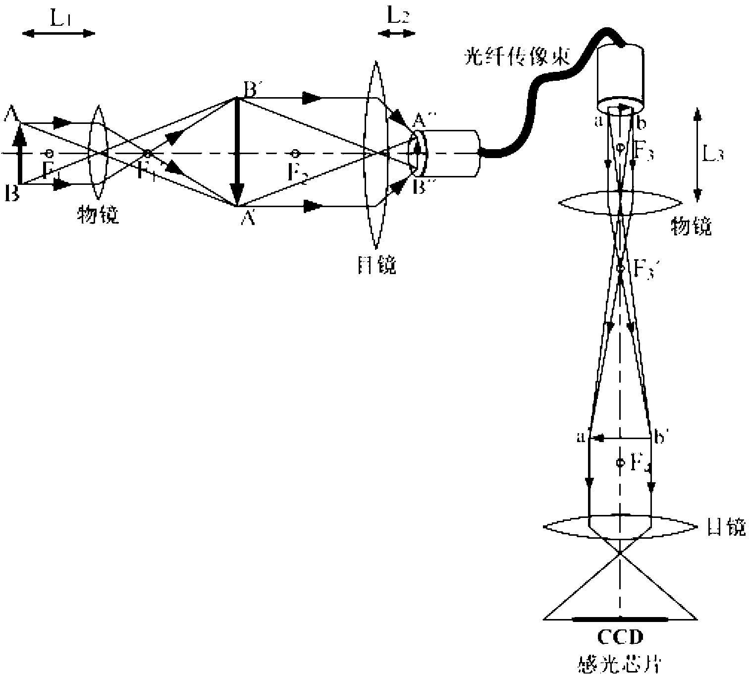
[0039] Specific implementation mode two: the following combination figure 2 This embodiment will be described. This embodiment will further describe the first embodiment. The vertical distance between the objective lens of the micromicroscope 7 and the sample to be measured in this embodiment is 20 mm to 22 mm.

specific Embodiment approach 3

[0040] Specific implementation mode three: the following combination figure 2 This embodiment will be described. The first embodiment will be further described in this embodiment. The distance between the eyepiece of the micromicroscope 7 and one end of the optical fiber image transmission bundle 5 in this embodiment is 5 mm to 7 mm.


PUM


Abstract

The invention discloses a structural dynamic defective optical fiber microscopic monitoring device, and belongs to the field of optics. The device solves the problem that the existing measuring device cannot monitor the surface state of the measuring device in a structural dynamic state. The device comprises a computer, a CCD (Charge Coupled Device) camera, an optical microscope, a fixed block, an optical fiber image bundle, an adapter, a miniature microscope, a close nipple, a two-dimensional fine adjustment system and a fixture, wherein the two-dimensional fine adjustment system comprises a longitudinal adjustment mechanism and a transverse adjustment mechanism; the fixture comprises a U-shaped groove and a locking knob; the bottom of the U-shaped groove of the fixture is fixedly connected with the two-dimensional fine adjustment system; an objective lens of the miniature microscope is embedded into one end of the close nipple; the other end of the close nipple is fixedly connected with a threaded through hole of the longitudinal adjustment mechanism; an ocular lens of the miniature microscope is communicated with one end of the optical fiber image bundle by the adapter; the other end of the optical fiber image bundle is communicated with an objective lens of the optical microscope by the fixed block; the CCD camera is arranged on an ocular lens side of the optical microscope; and the CCD camera is connected with the computer and used for monitoring component abrasion and defects.

Description

technical field [0001] The invention relates to an optical fiber microscopic monitoring device for structural dynamic defects, which belongs to the field of optics. Background technique [0002] The manufacture of mechanical components is mainly realized through welding, machining, casting and other processes. Due to the complexity and diversity of the production process, microscopic defects such as trachoma, scratches, cracks, and pits often appear on the surface of the components during the manufacturing process. . During the service process of mechanical components, these defects generated on the surface, due to the stress of high and low temperature, fatigue, corrosion, etc., microscopic defects develop into large defects, thereby reducing the corrosion resistance, wear resistance, fatigue limit, etc. of the components. The use performance directly affects the service life of the parts themselves, limits the performance of the equipment, and also brings great hidden dan...

Claims


Application Information

Patent Timeline
IPC IPC(8): G01N21/88G01N3/06
Inventor 刚铁朱荣华
Owner HARBIN INST OF TECH
Why Eureka
Try Eureka