Double-cantilever beam fiber grating acceleration sensor

An acceleration sensor, fiber grating technology, applied in the direction of acceleration measurement using inertial force, can solve the problems of acceleration measurement influence, poor torsional resistance, weak stability, etc., to improve stability, improve accuracy and stability, avoid The effect of fiber grating chirp effect

Inactive Publication Date: 2013-07-10
UNIV OF ELECTRONICS SCI & TECH OF CHINA
View PDF3 Cites 17 Cited by
  • Summary
  • Abstract
  • Description
  • Claims
  • Application Information

AI Technical Summary

Problems solved by technology

The second type is a single isosceles triangular beam. The stress of each point of this beam is uniform, but thi...

Method used


Image

  • Double-cantilever beam fiber grating acceleration sensor
  • Double-cantilever beam fiber grating acceleration sensor
  • Double-cantilever beam fiber grating acceleration sensor

Examples


Embodiment Construction

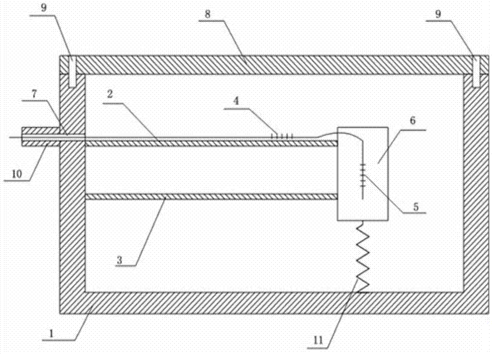
[0016] Such as figure 1 As shown, the fiber grating sensor includes a sensor housing 1, an upper cantilever beam 2, a lower cantilever beam 3, a sensing fiber grating 4, a reference fiber grating 5, a quality block 6, a fiber protection hole 7, a sealing cover 8, a screw 9, an optical fiber Protection tube 10, spring device 11;

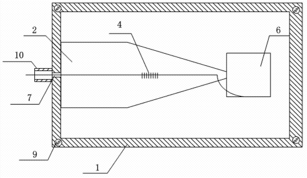
[0017] Two cantilever beams with the same shape are fixed on one side of the housing 1 , and the fixed ends of the cantilever beams are connected with the housing 1 as a whole. The two cantilever beams are parallel to each other and have exactly the same shape, which is a combined shape of a rectangle and an isosceles triangle, and are made of exactly the same elastic material. Insert the free ends of the two cantilever beams into the mass block 6, and connect with the mass block 6 as a whole.

[0018] Such as figure 2 As shown, the apex of the isosceles triangle vertex in the combined shape of the cantilever beam is the free end of the cantilever...


PUM


Abstract

The invention provides a double-cantilever beam fiber grating acceleration sensor which is good in stability and even in beam structural stress. An upper cantilever beam and a lower cantilever beam are of a shape of a combination of a rectangle and an equicrural triangle. Top points of top angles of the equicrural triangle are free ends, a bottom edge of the equicrural triangle is connected with a wide edge of the rectangle, and the length of the bottom edge of the equicrural triangle is the same with the length of the width of the rectangle. The other wide edge of the rectangle is a fixed end, and the height on the bottom edge of the equicrural triangle is larger than or equal to the length of the rectangle. When the height on the bottom edge of the equicrural triangle is larger than the length of the rectangle, the combination shape of the rectangle and the equicrural triangle can not only effectively avoid a chirp effect of the fiber grating but also greatly improve the stability of the sensor at the same time.

Description

technical field [0001] The invention belongs to the fiber grating sensing technology, in particular to the fiber grating acceleration sensing technology. Background technique [0002] Vibration measurement is a very important field in industrial production and scientific research. [0003] The fiber grating acceleration sensor includes two cantilever beams and a mass block, the mass block is welded between the two parallel cantilever beams through point contact, and the fiber grating is attached to the surface of the cantilever beam. When the sensor is vibrated, under the action of inertial force, the mass block drives the two rectangular beams to vibrate to generate strain, which is transmitted to the fiber grating to cause the wavelength shift, so as to measure the vibration. [0004] Since the fiber grating is sensitive to external changes, the wavelength drift of the fiber grating is easily affected by temperature during the measurement process. When the temperature ch...

Claims


Application Information

Patent Timeline
IPC IPC(8): G01P15/03
Inventor 位立丽吴宇饶云江
Owner UNIV OF ELECTRONICS SCI & TECH OF CHINA
Why Eureka
Try Eureka