
Control circuit for avoiding generation of overshoot of output voltage of power inverter

A technology of power converters and control circuits, which is applied in the direction of output power conversion devices and electrical components, and can solve problems such as error signal pull-down, influence, and damage to circuit components

Active Publication Date: 2015-01-07
RICHTEK TECH
View PDF4 Cites 0 Cited by
  • Summary
  • Abstract
  • Description
  • Claims
  • Application Information

AI Technical Summary

Problems solved by technology

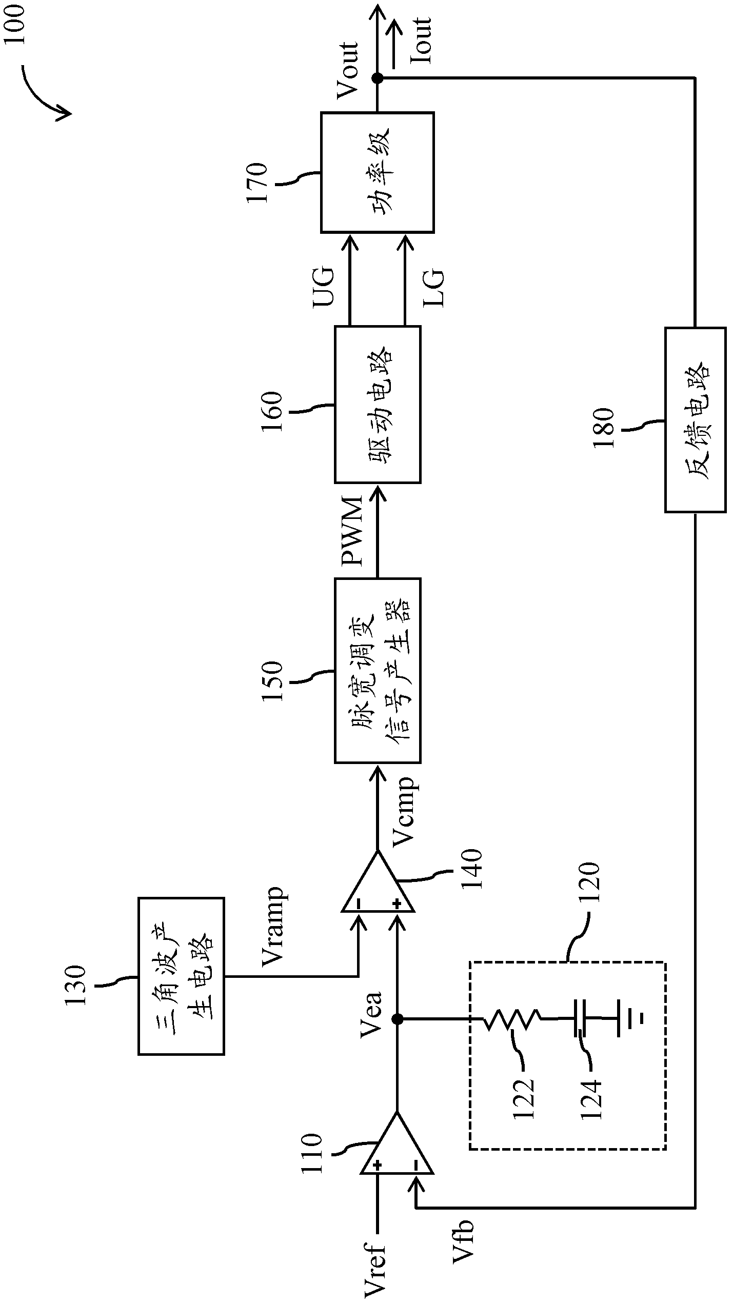
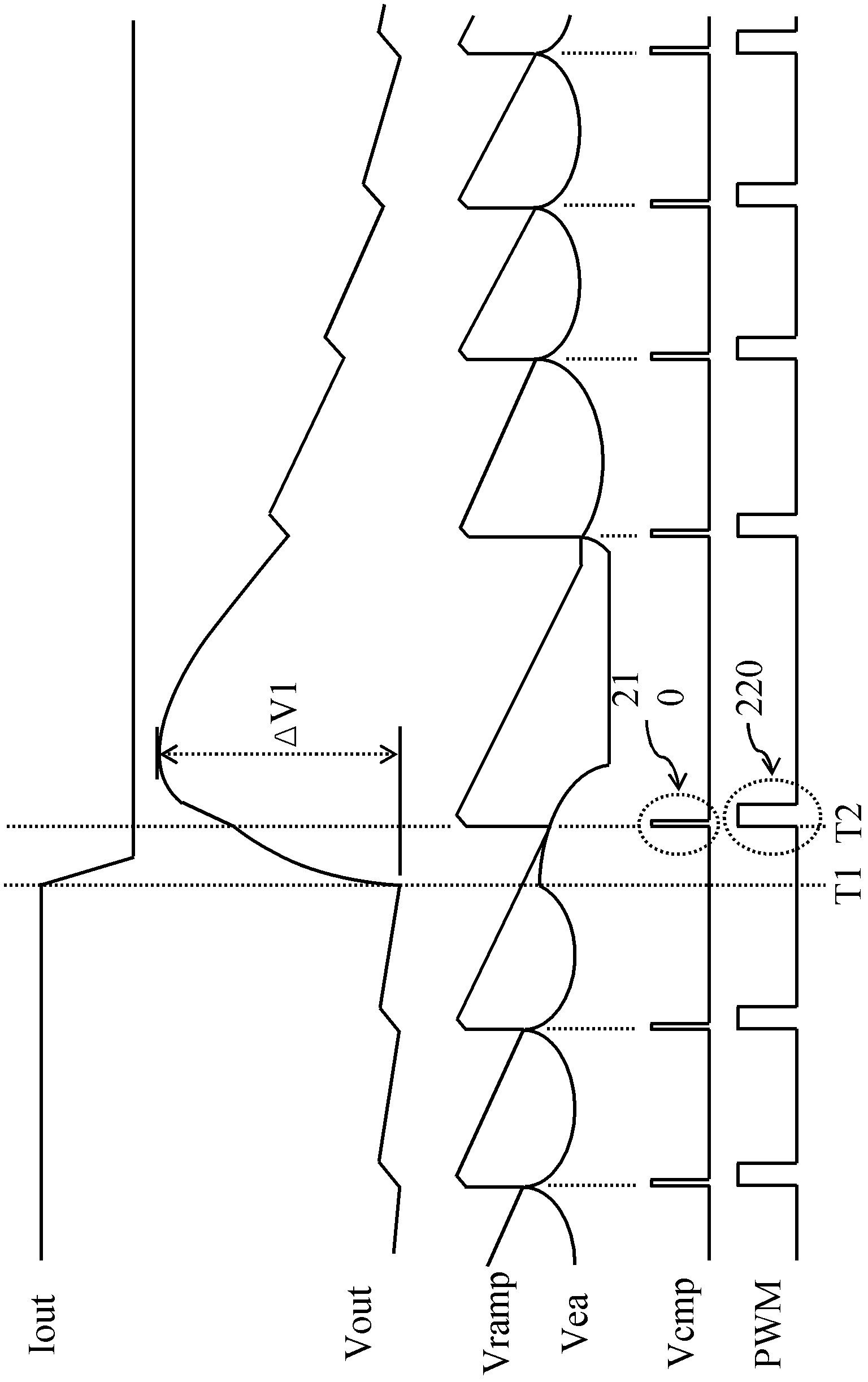
At this time, if the loop response of the power converter 100 is slow, not only the error signal Vea input to the positive terminal of the comparator 140 cannot be pulled down in time as the output voltage Vout gradually increases, but also the triangular wave signal Vramp input to the negative terminal of the comparator 140 will continue to decline with a negative slope due to the high-side switch in power stage 170 being turned off
In this way, it may happen that the level of the error signal Vea is greater than the level of the triangular wave signal Vramp (for example, the time T2 in 2), so that the comparator 140 outputs the redundant trigger pulse wave 210, resulting in the pulse width of the subsequent stage Modulation signal generator 150 outputs unexpected pulse wave 220 due to malfunction
The unexpected pulse wave 220 output by the pulse width modulation signal generator 150 will cause the voltage change ΔV1 of the output voltage Vout of the power stage 170 to be too large during the load transient process of the power converter 100 , and overshoot occurs. Exceeds the electrical specification range of the power converter 100 and may damage subsequent circuit components
[0005] Increasing the size of the output capacitor in the power stage 170 may reduce the possibility of the overshoot of the output voltage Vout of the power converter 100, but it will inevitably increase the area of ​​the circuit, and the loop response of the power converter 100 will also be affected. bad influence

Method used


Image

  • Control circuit for avoiding generation of overshoot of output voltage of power inverter
  • Control circuit for avoiding generation of overshoot of output voltage of power inverter
  • Control circuit for avoiding generation of overshoot of output voltage of power inverter

Examples


Embodiment Construction

[0024] Embodiments of the present invention will be described below in conjunction with related drawings. In these drawings, the same reference numerals indicate the same or similar elements or process steps.

[0025] When drawing a diagram, some signals will be amplified so that the content of the diagram can be clearly expressed. In addition, the shapes of some signals are simplified for ease of illustration. Therefore, the shape and relative size of each signal shown in the drawings should not be used to limit the scope of the present invention unless otherwise specified by the applicant. Furthermore, the invention may be embodied in many different forms, and the invention should not be construed as limited to the aspects of the exemplary embodiments set forth in this specification.

[0026] Certain terms are used in the specification and subsequent claims to refer to particular elements. It should be understood by those skilled in the art that the same element may be re...


PUM


Abstract

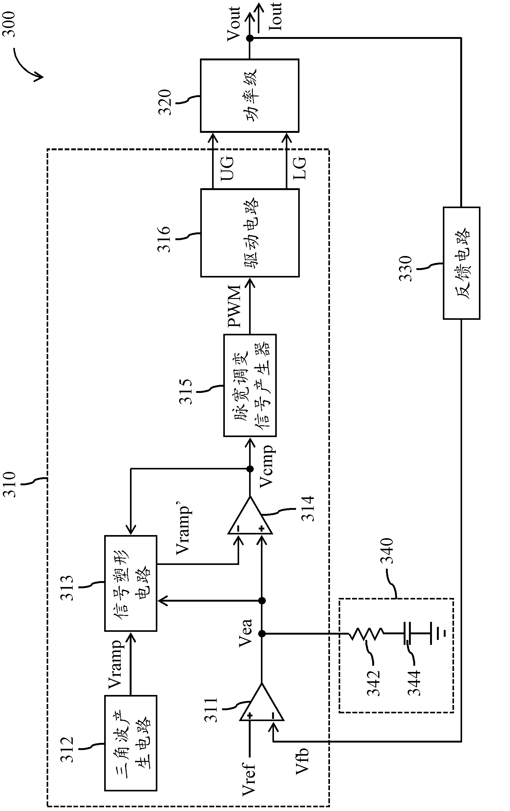
The invention provides a control circuit for avoiding generation of overshoot of an output voltage of a power inverter. The control circuit comprises an error amplifier, a triangular wave generating circuit, a signal shaping circuit, a comparator and a pulse width modulation signal generator. The error amplifier is used for generating an error signal according to a reference signal and the output voltage of the power inverter when the error amplifier is in coupling connection with the power inverter. The triangular wave generating circuit is used for generating a triangular wave signal. The signal shaping circuit is used for generating an alternative signal according to the triangular wave signal and fixing the alternative signal in a scheduled electrical level in the process that a load of the power inverter is transformed to a second lower load from a first load value. The comparator is used for comparing the error signal and the alternative signal so as to generate a comparison signal. The pulse width modulation signal generator is used for generating a pulse width modulation signal according to the comparison signal. Therefore, due to the operation of the signal shaping circuit, the problem of the generation of the overshoot of the output voltage of the power inverter is solved.

Description

technical field [0001] The invention relates to a power converter, in particular to a control circuit for preventing the output voltage of the power converter from overshooting. Background technique [0002] figure 1 is a functional block diagram of a conventional power converter 100 . The power converter 100 includes an error amplifier 110, a compensation circuit 120, a ramp signal generator 130, a comparator 140, a PWM signal generator 150, a driving circuit 160, a power stage 170, and Feedback circuit 180. The error amplifier 110 compares the reference signal Vref with the feedback signal Vfb generated by the feedback circuit 180 according to the output voltage Vout of the power converter 100 . The compensation circuit 120 converts the comparison result of the error amplifier 110 into an error signal Vea. exist figure 1 In , the equivalent resistance and equivalent capacitance in the compensation circuit 120 are denoted by numbers 122 and 124, respectively. The tria...

Claims


Application Information

Patent Timeline
Patent Type & Authority Patents(China)
IPC IPC(8): H02M1/32
Inventor 陈文玮
Owner RICHTEK TECH
Learn More