Light emitting and receiving device with high flexibility and achieving method thereof

A high-sensitivity, transmitting-receiving technology, applied in electromagnetic transceivers, wavelength division multiplexing systems, etc., can solve the problems of reducing the implementation cost of optical transmitting and receiving devices, and achieve the effect of high gain and noise index

Active Publication Date: 2013-07-10
WUHAN POST & TELECOMM RES INST CO LTD
View PDF6 Cites 9 Cited by
  • Summary
  • Abstract
  • Description
  • Claims
  • Application Information

AI Technical Summary

Problems solved by technology

[0004] The technical problem to be solved by the present invention is to solve the problem of how to reduce the realization cost of a high-sensitivity optical transmitting and receiving device

Method used


Image

  • Light emitting and receiving device with high flexibility and achieving method thereof
  • Light emitting and receiving device with high flexibility and achieving method thereof
  • Light emitting and receiving device with high flexibility and achieving method thereof

Examples


Embodiment 1

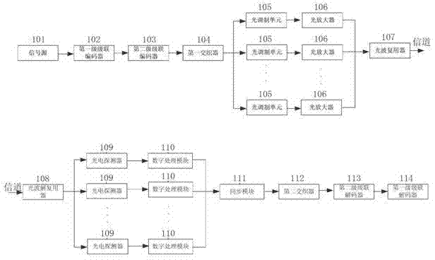
[0024] Such as figure 1 As shown, the high-sensitivity optical transmitting and receiving device provided by the present invention includes a transmitting end and a receiving end connected by an optical channel, and the transmitting end includes a signal source 101, a first-stage cascaded encoder 102, an electro-optical modulation and repetition encoding unit and a light wave A multiplexer 107, wherein the concatenated encoder includes a first-stage concatenated encoder 102 and a second-stage concatenated encoder 103 . The electro-optical modulation and repetition encoding unit includes a second-stage cascaded encoder 103 , a first interleaving unit 104 , a multi-channel optical modulation unit 105 and an optical amplifier 106 .

[0025] The electrical signal (data signal) generated by the signal source 101 is encoded by the first-stage cascade encoder 102 and the second-stage cascade encoder 103 to form an electrical signal with repetitive code characteristics, wherein the se...

Embodiment 2

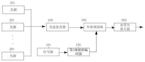
[0029] The difference between this embodiment and Embodiment 1 is that the electrical signal with repetition code characteristics is modulated into a multi-channel optical signal with repetition code characteristics by the external modulator and broadband optical amplifier, and the external modulator can use an intensity modulator based on MZM Or an IQ modulator, an external modulator is usually better, but needs to be paired with a separate light source.

[0030] Such as figure 2 As shown, the multi-light source 201 is sent to the external modulator 202 after being multiplexed by the optical multiplexer 108. The signal source 101 is first encoded by the first-stage cascaded encoder 102, and then directly drives the external modulator 202 to be modulated to have a repetitive The multi-channel optical signals with code characteristics are sent to the channel after passing through the broadband optical amplifier 203. With this structure, only one external modulator can be used...


PUM


Abstract

The invention discloses a light emitting and receiving device with high flexibility and an achieving method thereof. The method comprises the following steps that an electric signal generated by a signal source is encoded by a first-stage cascade encoder and is modulated by electro-optical modulation and repetition coding units to be multipath optical signals with repetition code characteristics, the multipath optical signals are finally multiplexed to be optical wave signals to be sent out, the number of the electro-optical modulation and repetition coding units is N, encoding load is (N-1) / N; and the optical wave signals sent by optical channels are multiplexed, multipath partial wave signals are obtained, then the multipath partial wave signals are recovered to a corresponding electric signals by a multipath photoelectricity detector, finally the electric signals are subjected to interweave combination and decoded by the cascade encoder, and corresponding electric signals are obtained. The light emitting and receiving device with high flexibility and the achieving method adopt a multiplying method and enable the independent error rate of each channel to be far smaller than the signal error rate of the whole broadband so as to fully utilize coding gain brought by high coding load. The light emitting and receiving device normally works under the environment with low optical signal to noise ratio.

Description

technical field [0001] The invention relates to light sending and receiving technology, in particular to a high-sensitivity light sending and receiving device and a realization method. Background technique [0002] In the construction of communication systems in some special occasions (coastal, island, desert, etc.), due to some special reasons, an end-to-end direct path must be established between sites without any relay equipment in between, so the optical signal will be greatly reduced during transmission. Attenuation, therefore, requires high-gain amplification at the receiving end to enable the photodetector to detect the signal. However, this will introduce a large amount of noise, degrade the signal-to-noise ratio of the signal, and thereby reduce the performance of the communication system. [0003] In the field of optical space communication, the signal at the receiving end also faces the same problem. The current main method is to improve the signal-to-noise rati...

Claims


Application Information

Patent Timeline
Patent Type & Authority Applications(China)
IPC IPC(8): H04B10/40H04J14/02
Inventor 胡荣杨奇肖潇杨铸
Owner WUHAN POST & TELECOMM RES INST CO LTD
Why Eureka
Try Eureka