Manual-pneumatic bi-component spray gun

A two-component, dual-purpose technology, applied in the direction of spraying devices, liquid spraying devices, single handheld devices, etc., can solve the problems of inconvenient construction, inconvenient use, and inability to adjust the flow rate online in real time, and achieve a simple and reasonable structure. convenient effect

Inactive Publication Date: 2013-07-17
吴祎
View PDF8 Cites 9 Cited by
  • Summary
  • Abstract
  • Description
  • Claims
  • Application Information

AI Technical Summary

Problems solved by technology

[0002] The traditional high-pressure spraying or pouring of polyurethane foam mainly adopts two-component air-cleaning or mechanical cleaning spray guns. Although foam with good performance can be obtained, it has the following disadvantages: 1) The weight of the spray gun is caused by the need to use compressed air to control the switch spray gun. 2) When adjusting the size of the output flow, the mixing chamber of different specifications must be replaced, and the flow cannot be adjusted in real time online; 3) The shape of the spray surface depends on the mixing chamber, and the user cannot adjust it by himself
Therefore, the inconvenient use of traditional two-component spray guns limits the wide application of high-performance foam coatings in thermal insulation and other aspects.

Method used


Image

  • Manual-pneumatic bi-component spray gun
  • Manual-pneumatic bi-component spray gun
  • Manual-pneumatic bi-component spray gun

Examples


Embodiment Construction

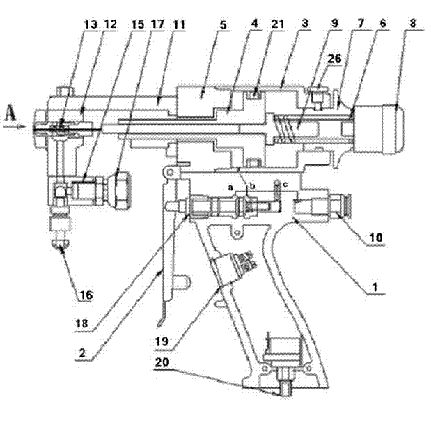
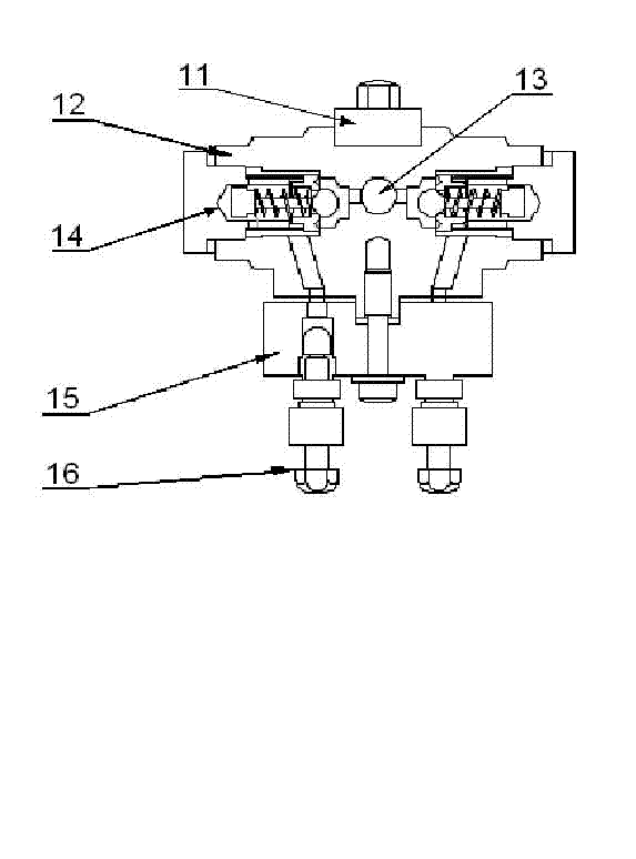
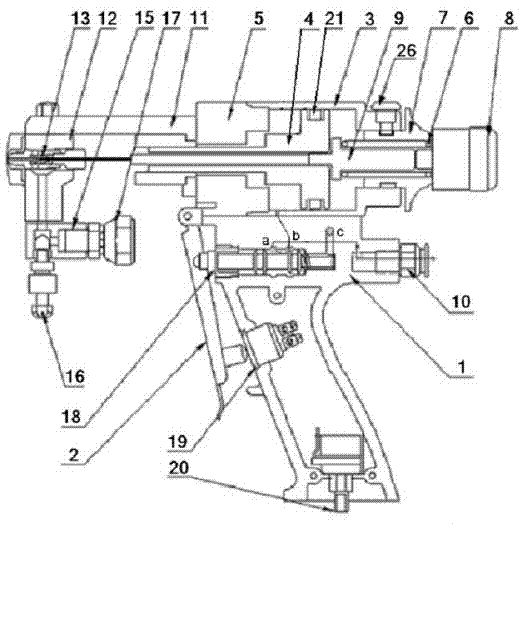
[0018] The accompanying drawing discloses a non-limiting schematic diagram of the specific structure of an embodiment of the present invention.

[0019] Referring to the accompanying drawings, 1 in the figure is the gun handle, 2 is the trigger, 3 is the cylinder barrel, 4 is the piston, 5 is the gun body, 6 is the return spring, 7 is the spring jacket, 8 is the valve stem adjustment button, and 9 is the Valve stem, 10 is the air pipe joint, 11 is the beam, 12 is the gun head, 13 is the mixing chamber, 14 is the filter check valve, 15 is the connection block, 16 is the manual valve, 17 is the feed joint, 18 is the pilot valve , 19 is a remote control switch, 20 is an adjustment knob, 21 is a seal, 22 is a sleeve pull rod, 23 is a rear limit plate of the pull rod, 24 is a pull rod adjusting nut, 25 is a pull rod handle, and 26 is an assembly positioning bolt.

[0020] The hand-pneumatic dual-purpose two-component spray gun of the present invention includes a gun head part, a gu...


PUM


Abstract

A manual-pneumatic bi-component spray gun comprises a gun head unit, a gun body, a cylinder barrel, a piston, a valve rod and a gun handle unit, and further comprises a valve rod pneumatic-control assembly and a valve rod manual-control assembly. The valve rod pneumatic-control assembly or the valve rod manual-control assembly is mounted on the cylinder barrel at the tail end of the valve rod through a component-positioning bolt, the front portion of the cylinder barrel is mounted on the gun body, the piston is fixedly mounted in the middle of the valve rod and further mounted in the cylinder barrel through a sealing element, the front end of the valve rod extends out of the gun body to be inserted into a mixing chamber of the gun head unit which is fixedly arranged at the front end of the gun body through a horizontal beam, and the gun handle unit is mounted on the lower portion of the gun body. Since the valve rod pneumatic-control assembly and the valve manual-control assembly are additionally arranged, the bi-component spray gun can be automatically controlled by compressed air or can be controlled manually, carrying a heavy air compressor at any time can be avoided, spraying surface area can be regulated, the mixing chamber can be cleaned automatically and remote control of a spraying machine can be performed; and the manual-pneumatic bi-component spray gun is simple in structure, and convenient to use.

Description

technical field [0001] The invention relates to a high-pressure two-component chemical material spray gun for spraying and pouring materials such as polyurethane foam, in particular to a two-component spray gun capable of manual or pneumatic dual-purpose, and belongs to the field of heat preservation and waterproof machinery. Background technique [0002] The traditional high-pressure spraying or pouring of polyurethane foam mainly adopts two-component air-cleaning or mechanical cleaning spray guns. Although foam with good performance can be obtained, it has the following disadvantages: 1) The weight of the spray gun is caused by the need to use compressed air to control the switch spray gun. 2) When adjusting the size of the output flow, the mixing chamber of different specifications must be replaced, and the flow cannot be adjusted in real time online; 3) The shape of the spray surface depends on the mixing chamber, and the user cannot adjust it by himself. Therefore, the ...

Claims


Application Information

Patent Timeline
Patent Type & Authority Applications(China)
IPC IPC(8): B05B7/04B05B11/02B05B12/00B05B15/02
Inventor 吴祎
Owner 吴祎
Why Eureka
Try Eureka