Automatic centering coiling device and method for hot rolled coil separating line

A middle-rolling and sub-coiling technology, applied in rolling mill control devices, guiding/positioning/aligning devices, metal rolling, etc., to solve problems such as smashing machinery and equipment, falling steel coils, and deviating from the center position. , to achieve the effect of ensuring equipment and personal safety, improving equipment operation rate, and reducing the probability of falling

Active Publication Date: 2013-07-17
ANGANG STEEL CO LTD
View PDF5 Cites 8 Cited by
  • Summary
  • Abstract
  • Description
  • Claims
  • Application Information

AI Technical Summary

Problems solved by technology

The positioning error caused by the mechanical clearance and mechanical friction of the coiler with the hydraulic motor as the transmission device often causes the position of the coiler to transport the steel coil to the preparation station to deviate from the center position of the preparation station.
Since the position of the steel coil at the preparation station is not accurate, the operator needs to manually adjust the position of the steel coil; when the position of the steel coil is too far away from the center line of the preparation station, the steel coil may even fall from the preparation station, resulting in smashing mechanical equipment accident
In addition, after the reel car receives the command to stop the hydraulic motor, due to the inertia generated by its own weight and coil weight, the reel car cannot stop immediately
When the coiling car stops, the deviation between the center line of the coiling car and the center line of the preparation station is about ±300mm, and the serious deviation of the two center lines may easily cause the steel coil to fall from the preparation station or cut the head of the steel coil in the next step make an impact

Method used


Image

  • Automatic centering coiling device and method for hot rolled coil separating line
  • Automatic centering coiling device and method for hot rolled coil separating line

Examples


Embodiment Construction

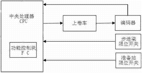
[0028] Depend on figure 1 It can be seen that the automatic centering and coiling device of the hot-rolled coiling line of the present invention is mainly based on the original CPU (central processing unit) and the coiling car, and an incremental encoder is installed in the horizontal running direction of the coiling car. WLCA32-43 travel limit switches are respectively set on the center line of the entrance walking beam and the center line of the preparation station. At the same time, a function control block FC is added to the CPU, and the encoder and two limit switches are respectively connected to the function control block. FC connection.

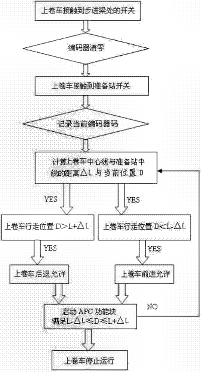
[0029] The specific implementation method and steps of the automatic centering and winding method of the hot rolling sub-coil line of the present invention are:

[0030] First, install the windshield iron on the winding car. When the coiling car runs to the position where its center line coincides with the center line of the preparat...


PUM


Abstract

The invention provides an automatic centering coiling device and method for a hot rolled coil separating line. An encoder is arranged in the operation direction of a coiling reel; limiting switches are arranged on central lines of an inlet stepping beam and a preparation station respectively; a coiling reel automatic positioning control program is added in an addition function control block FC; and the actual stop position D of the coiling reel is set to meet the formula that the D is greater than or equal to L-delta L, but less than or equal to L+delta L. When a stop iron of the coiling reel is in contact with the limiting switch on the stepping beam, the code value of the encoder is cleared; when the stop iron of the coiling reel is in contact with the limiting switch of the preparation station, the initial code value X is recorded; when the coiling reel is stopped, the code value Y is recorded timely, and the position deviation delta L of the coiling reel and the stop position D of the coiling reel are calculated; if D is greater than L+delta L, a set draw-back distance of the coiling reel is controlled; and if the D is less than L+delta L, a set advancing distance of the coiling reel is controlled. Therefore, the position deviation of the coiling reel is controlled to be within + / -50 mm, the coiling time is shortened, the equipment operation rate is improved and the steel coil falling accidents are avoided.

Description

technical field [0001] The invention belongs to the field of automatic control of steel rolling, and in particular relates to an automatic centering device and method for coil winding of a hot-rolled sub-coil line. Background technique [0002] At present, the position control method adopted by domestic hot-rolled sub-coil line coiler is mainly controlled by two kinds of position detection switches: one is to use the mechanical travel switch, and when the iron stopper installed on the coiler touches the mechanical travel switch, The physical normally open contact of the switch is closed, and the logic controller cuts off the action control voltage of the hydraulic motor to stop it from running. The second is to choose an electromagnetic proximity switch. The distance of the electromagnetic proximity switch is 25mm. Install a ferrous material stopper on the winding car, and install it at a distance less than 25mm from the position of the detection switch. When the winding car...

Claims


Application Information

Patent Timeline
Patent Type & Authority Applications(China)
IPC IPC(8): B21B37/00B21B39/14B21C47/24
Inventor 张成斌赵久长张红军吴迪李章安孙伟
Owner ANGANG STEEL CO LTD
Why Eureka
Try Eureka