Rotary three-dimensional piezoelectric force measurement cutter handle device

A rotating, three-dimensional technology, applied in the direction of measuring/indicating equipment, metal processing machinery parts, metal processing equipment, etc., can solve problems such as wireless signal transmission, and achieve the effect of improving measurement accuracy

Inactive Publication Date: 2013-07-17
DALIAN UNIV OF TECH
View PDF10 Cites 19 Cited by
  • Summary
  • Abstract
  • Description
  • Claims
  • Application Information

AI Technical Summary

Problems solved by technology

The dynamometer tool holder utilizes the characteristics that the inner and outer rings of deep groove ball bearings can rotate relative to each other and the inner and outer rings are always in contact with the steel balls. Three lightweight deep groove ball bearings are used as the charge signal transmission tools of the piezoelectric sensor to...

Method used


Image

  • Rotary three-dimensional piezoelectric force measurement cutter handle device

Examples


Embodiment Construction

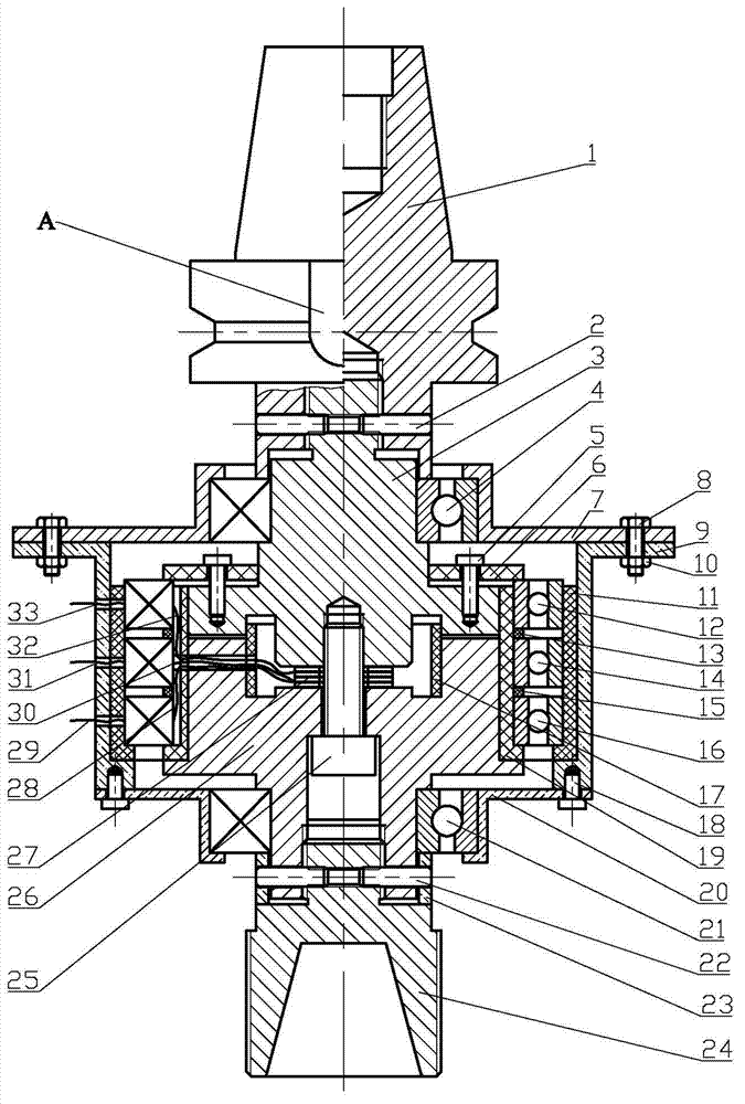
[0013] combined with figure 1 and the technical scheme describe in detail the implementation of the present invention. When milling parts and measuring the cutting force and torque during the milling process, connect the internal thread of the upper end 1 of the milling tool holder of the rotary three-dimensional piezoelectric force measuring tool holder device with the drawing thread, so that the arc shape of the upper end 1 of the milling tool holder Groove A aligns with the positioning block at the end of the machine tool spindle for positioning. The lower end 24 of the handle of a knife cooperates with the tool holder to clamp the tool.

[0014] During processing, the rotation of the main shaft drives the upper end 1 of the milling cutter shank to rotate, and the sensor part connected thereto includes the sensor upper housing 3, the three-dimensional piezoelectric quartz measurement crystal group 27, the inner lead wire 28 of the torque signal, the inner lead wire 30 of t...


PUM


Abstract

The invention discloses a rotary three-dimensional piezoelectric force measurement cutter handle device, belonging to the field of a force measurement device of a piezoelectric sensor, and particularly relates to a device for directly measuring an axial force, a tangential force and a torque applied to a cutter in a machining process such as milling and drilling. The device is composed of a replaceable milling cutter handle upper end, a piezoelectric sensor part, a signal transmission part and a cutter handle lower end, wherein the piezoelectric sensor part is composed of a sensor upper shell, a three-dimensional piezoelectric quartz measuring crystal group, an insulating sleeve, a sensor lower shell, a tangential force, an axial force, a torque signal inner lead wire and the like. By using three bearings to respectively serve as output paths for the axial force, the tangential force and the torque signal of the piezoelectric sensor, the rotary three-dimensional piezoelectric force measurement cutter handle device solves the signal wireless transmission problem when the piezoelectric sensor is arranged on a main shaft of a machine tool. The rotary three-dimensional piezoelectric force measurement cutter handle device reduces damage from cutting and a cutting liquid to a force measurement instrument, is suitable for monitoring a cutting force in the processing of precise parts, and improves the cutting automation level.

Description

technical field [0001] The invention belongs to the field of force-measuring devices in piezoelectric sensors, in particular to a device for directly measuring the axial force, tangential force and torque suffered by a tool during machining processes such as milling and drilling. Background technique [0002] At present, there are two main methods for measuring cutting force in machining: strain type and piezoelectric type. [0003] In the strain type, the force measuring instrument with the strain gauge as the sensitive element has the advantages of simple structure, small size, stable and reliable performance, and convenient use. It is generally measured by the principle that the strain gauge deforms after being stressed and the resistance value changes Force, widely used in force signal measurement. However, since the resistance value can only change when the strain gauge produces strain, usually tens to 20,000 microstrains, the higher the sensitivity of the strain gauge...

Claims


Application Information

Patent Timeline
IPC IPC(8): B23Q17/09
Inventor 任宗金贾振元尚永艳高翼飞高胜南卢晓红
Owner DALIAN UNIV OF TECH
Why Eureka
Try Eureka