Steel ball conveyor device

A conveying device and steel ball technology, applied in furnaces, heat treatment equipment, heat treatment furnaces, etc., can solve problems such as lack of corresponding enlightenment, and achieve the effects of convenient operation and maintenance, concise overall structure, and reliable transmission coordination.

Active Publication Date: 2013-07-17
CHANGSHU FEIFAN METALWORK
View PDF7 Cites 18 Cited by
  • Summary
  • Abstract
  • Description
  • Claims
  • Application Information

AI Technical Summary

Problems solved by technology

However, there is no corresponding revelation in the published patents and non-patent literature on the measures to protect these factors

Method used


Image

  • Steel ball conveyor device
  • Steel ball conveyor device
  • Steel ball conveyor device

Examples


Embodiment

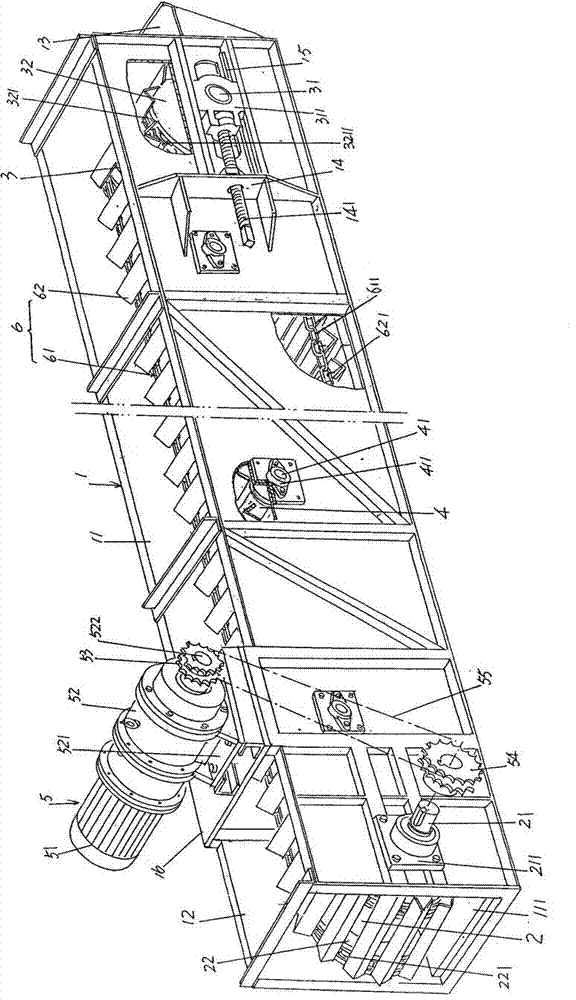
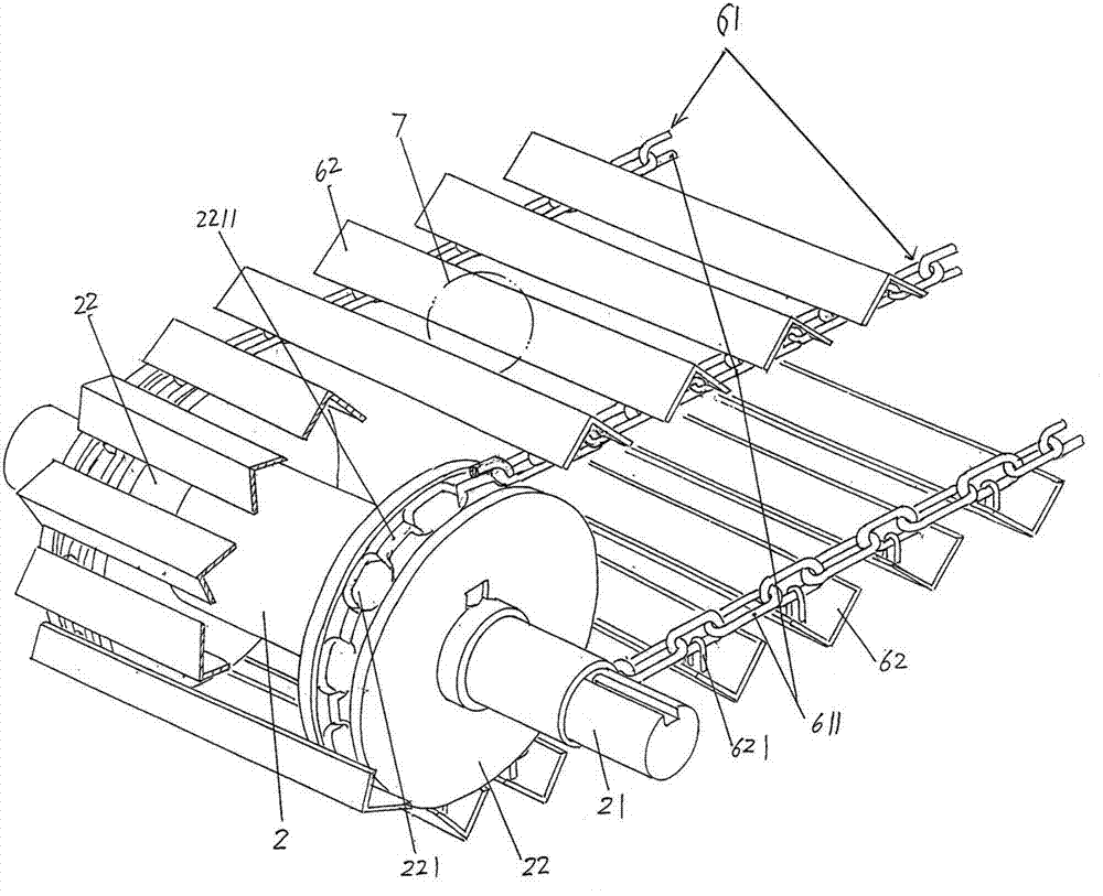
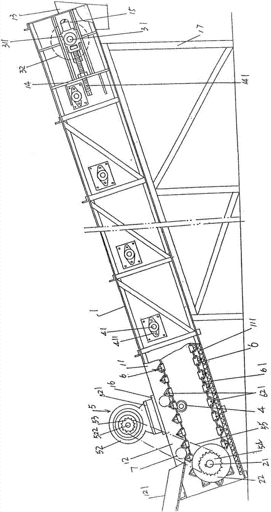
[0015] See figure 1 and figure 2 ,exist figure 1 Among them, a delivery box 1 is provided, the upper part of the longitudinal direction of the delivery box 1 is preferably not closed, and the upper part of one end of the delivery box 1 is formed as a ball entry port 12, and the ball entry port 12 is equipped with Set guide ball groove 121 ( image 3 shown) the quenched steel ball 7 from the quenching mechanism ( image 3 Shown) introduce the steel ball carrying mechanism 6 that also will be described in detail below. A ball unloading bucket 13 is disposed on the end face of the other end of the delivery box 1, and a wear-resistant plate 111 is laid on the bottom of the delivery box cavity 11 of the delivery box 1. In this embodiment, the wear-resistant plate 111 uses a smooth surface. Granite or marble, and the thickness is preferably 1-3 cm, preferably 1.5-2.5 cm, most preferably 2 cm (2 cm in this embodiment).

[0016] A main drive roller 2 is provided, and one end of ...


PUM

PropertyMeasurementUnit
thicknessaaaaaaaaaa

Abstract

The invention discloses a steel ball conveyor device belonging to the field of conveying machinery. The steel ball conveyor device comprises a conveying box, a main driving roller, a direction-changing driving roller, a group of carrier rollers, a power transmission mechanism and a steel ball carrying mechanism, wherein a wear-resisting plate is arranged in a conveying cavity of the conveying box; the main driving roller is supported on the wall of the conveying box; chain traction chain sprockets are respectively formed at the two ends of the main driving roller; the direction-changing driving roller is supported on the wall of the conveying box; chain direction-changing traction chain sprockets are respectively formed at the two ends of the direction-changing driving roller; the group of carrier rollers are supported in the middle of the conveying box; the power transmission mechanism is arranged on the top of the conveying box; the steel ball carrying mechanism comprises a pair of curtain rail plate traction chains and a group of curtain rail plates; the direction-changing driving roller is supported on a direction-changing driving roller shaft head support bearing seat; the direction-changing driving roller shaft head support bearing seat is arranged a guide rail; the guide rail is arranged on the wall of the conveying box; the wall of the conveying box is provided with an adjusting screw rod seat which is provided with an adjusting screw rod; and the pair of curtain rail plate traction chains are respectively formed by chain links which are connected in a circulating way. The steel ball conveyor device is beneficial to unloading a steel ball, reliable in transmission and matching, good in firmness and long in service life, can guarantee the traction effect for the curtain rail plates, and is simple and convenient to operate, examine and maintain.

Description

technical field [0001] The invention belongs to the technical field of conveying machinery, and in particular relates to a steel ball conveying device, which is used for conveying steel balls quenched by a steel ball quenching machine to a tempering furnace for tempering. Background technique [0002] A complete steel ball production line usually includes a heating furnace for heating bars (also known as round steel) (such as Chinese patent ZL201120027307.2), a ball forming machine for rolling the bars heated by the heating furnace into steel balls ( Such as Chinese patents ZL200710023538.4Z and L201010239364.7, etc.), a quenching machine for quenching steel balls rolled by a ball forming machine (such as Chinese patents ZL200720131309.X and ZL200720131310.2, etc.) and a quenching machine for quenching A tempering furnace for tempering steel balls after quenching (such as Chinese patents ZL201010576110.4 and ZL201110029183.6, etc.). Since the medium used for quenching the s...

Claims


Application Information

Patent Timeline
Patent Type & Authority Applications(China)
IPC IPC(8): C21D9/36
Inventor 陈刚
Owner CHANGSHU FEIFAN METALWORK
Why Eureka
Try Eureka