Seepage-proof water-stop cushion for inspection shaft

A technology for water-stop pads and inspection wells, applied in water conservancy projects, underwater structures, artificial islands, etc., can solve problems affecting the solidity of the foundation around the well wall, easy collapse of the rammed earth layer, and affecting the stability of the inspection well foundation, etc.

Inactive Publication Date: 2013-07-17
詹春生
View PDF6 Cites 3 Cited by
  • Summary
  • Abstract
  • Description
  • Claims
  • Application Information

AI Technical Summary

Problems solved by technology

In the rainy season, the rainwater will seep down along the above gaps or fissures, and the long-term effect will affect the solidity of the foundation around the well wall. In addition, the inspection well has been crushed by vehicles for a long time. Over time, the rammed earth layer around the inspection well will easily collapse. Even affect the stability of the inspection well foundation

Method used


Image

  • Seepage-proof water-stop cushion for inspection shaft
  • Seepage-proof water-stop cushion for inspection shaft
  • Seepage-proof water-stop cushion for inspection shaft

Examples


Embodiment 1

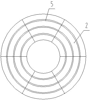
[0014] Embodiment one: if figure 1 , figure 2 and image 3 As shown, the anti-seepage and water-proof pad for inspection well of the present invention includes a backing plate made of elastic flexible material, and the center of the backing plate is provided with a circular through hole 7, and the outer ring of the backing plate has the same shape as the through hole 7. The shape and size of the through hole 7 are identical to the shape and size of the inspection shaft inner wall cross section, the shape and size of the backing plate outer ring is greater than the shape and size of the inspection shaft outer wall cross section, and the backing plate is provided with a pressure rib 1.

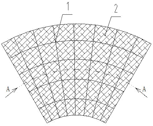
[0015] The backing plate is composed of at least two fan-shaped plates 2 of the same size, figure 1 There are six fan-shaped plates 2 in the middle, and the two sides of the same surface of each fan-shaped plate 2 are respectively provided with a card groove 3 and a card bar 4 along the radia...

Embodiment 2

[0019] Embodiment two: if figure 1 , figure 2 and Figure 4 As shown, the difference from the first embodiment is that the surface of each fan-shaped plate 2 is provided with a groove 6 , and the groove 6 is an arc-shaped structure along the circumferential direction of the fan-shaped plate 2 .

Embodiment 3

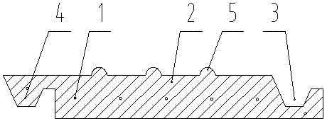
[0020] Embodiment three: as figure 1 , figure 2 and Figure 5 As shown, the difference from Embodiment 1 is that the surface of each fan-shaped plate 2 is provided with ribs 5 and grooves 6, and the ribs 5 and grooves 6 are arc-shaped structures along the circumferential direction of the fan-shaped plate 2. .


PUM


Abstract

The invention discloses a seepage-proof water-stop cushion for an inspection shaft. The seepage-proof water-stop cushion comprises a cushion plate made of elastic flexible materials, wherein a round, fan-shaped or rectangular through hole is formed in the center of the cushion plate; the outer ring of the cushion plate has the same shape as the through hole; the size of the through hole is same as that of the cross section of the inner wall of the inspection shaft; and the size of the outer ring of the cushion plate is greater than that of the cross section of the outer wall of the inspection shaft. According to the technical scheme, the cushion plate is laid between the upper surface of a walling crib of the inspection shaft and the lower surface of a well lid base, the edge of the inner ring of the cushion plate is consistent with the inner ring of the inspection shaft wall, and the outer edge of the cushion plate is laid between a roadbase and a pavement, so that the elastic sealing function of the cushion plate can effectively prevent rainwater on the pavement from seeping along the crack and gap between the outer side of the inspection shaft wall and the pavement, a rammed earth layer around the inspection shaft is prevented from losing strength after long-term immersion by rainwater, the roadbase can maintain favorable consistency and bearing capacity all along, the smoothness of a road can be maintained, the inspection shaft can be protected, and the service life of the inspection shaft can be prolonged.

Description

technical field [0001] The invention belongs to the technical field of civil construction, and in particular relates to an anti-seepage and water-proof pad for inspection wells. Background technique [0002] At present, the materials of well rings and manhole cover bases of inspection wells on urban roads are generally prefabricated concrete, metal or plastic, which are different from asphalt pavement, have different characteristics of thermal expansion and contraction, and belong to different processing procedures and During a certain period of time, under the action of dynamic load for a certain period of time, gaps or cracks will be formed between the base of the manhole cover or the well ring and the road surface and base. In the rainy season, the rainwater will seep down along the above gaps or fissures, and the long-term effect will affect the solidity of the foundation around the well wall. In addition, the inspection well has been crushed by vehicles for a long time....

Claims


Application Information

Patent Timeline
Patent Type & Authority Applications(China)
IPC IPC(8): E02D29/12
Inventor 詹春生
Owner 詹春生
Why Eureka
Try Eureka