Mould-clamping oil cylinder device

A technology of clamping cylinder and guide ring, applied in the direction of fluid pressure actuating device, etc., can solve the problems of clamping cylinder failure, sealing damage of clamping cylinder, strain, etc., and achieve the effect of not easy oil leakage and large buffer space.

Inactive Publication Date: 2013-07-17
KEDA INDUSTRIAL GROUP CO LTD
View PDF8 Cites 2 Cited by
  • Summary
  • Abstract
  • Description
  • Claims
  • Application Information

AI Technical Summary

Problems solved by technology

[0008] like figure 1 and 2 As shown, in the process of the movable beam 1 and the fixed beam 2 extruding the mold 6, the force on the fixed beam 2 will produce a slight bending in the direction shown by the dotted line in the figure, and then drive the front end cover 51, cylinder barrel 52, and the connecting cover 56 deflect together, but the piston rod 53, the piston 54, and the main nut 55 are fixed on the pull rod 3 and will not deflect together with the fixed beam 2, which will cause an angle to be formed between the piston 54 and the cylinder barrel 52. Now Due to the small gap between the piston 54 and the cylinder barrel 52 and the small gap between the piston rod 53 and the front end cover 51 in some oil cylinder structures, the seal of the mold clamping cylinder is often damaged. What is more serious is that when the fixed beam deforms greatly, the piston The gap between 54 and the cylinder 52 will no longer exist, so the inner wall of the cylinder 52 will be strained, resulting in failure of the clamping cylinder

Method used


Image

  • Mould-clamping oil cylinder device
  • Mould-clamping oil cylinder device
  • Mould-clamping oil cylinder device

Examples


Embodiment 1

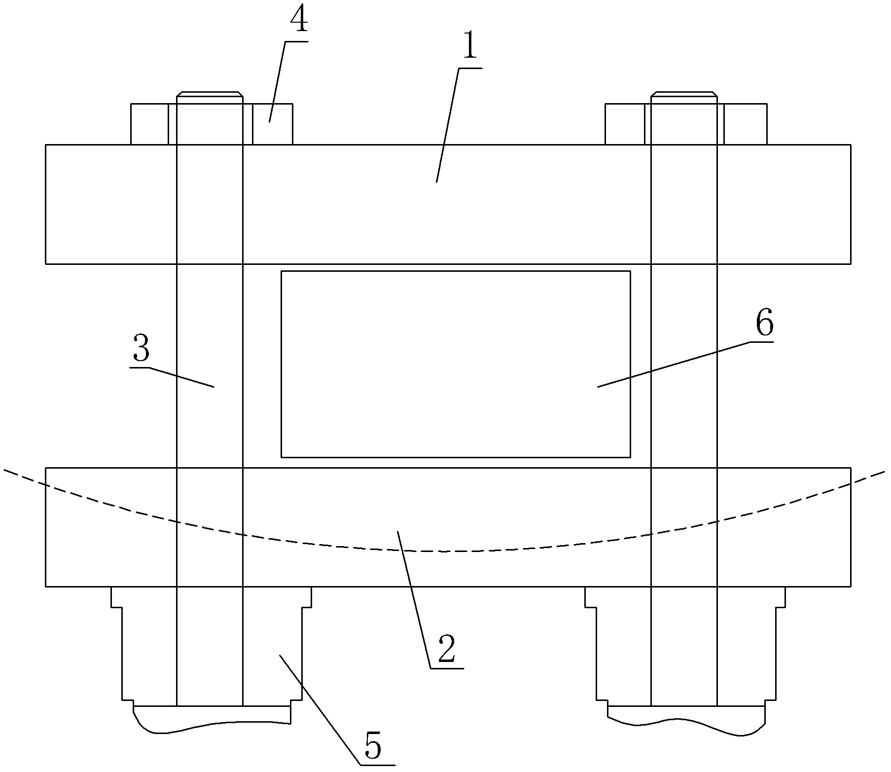
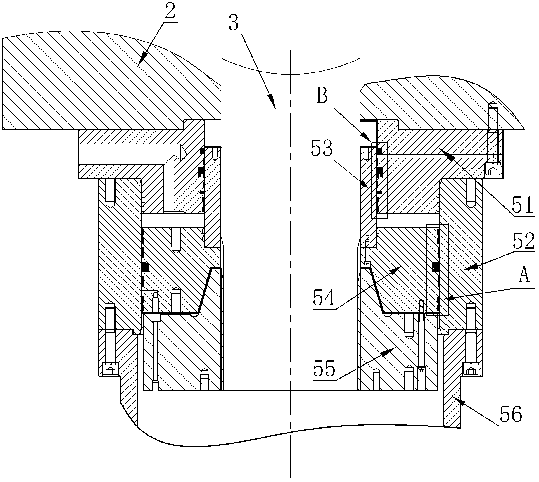
[0039] like figure 2 As shown, the main structure of the clamping cylinder device of the present invention still includes a cylinder 52, a front end cover 51 connected to the front end of the cylinder 52 by screws, a piston rod 53 sleeved on the pull rod 3, and a piston connected to the piston rod 53 by screws. 54, and the main nut 55 that is connected to the tail end of the pull rod 3, and the connection cover 56 that is connected to the rear end of the cylinder barrel 52 by screws.

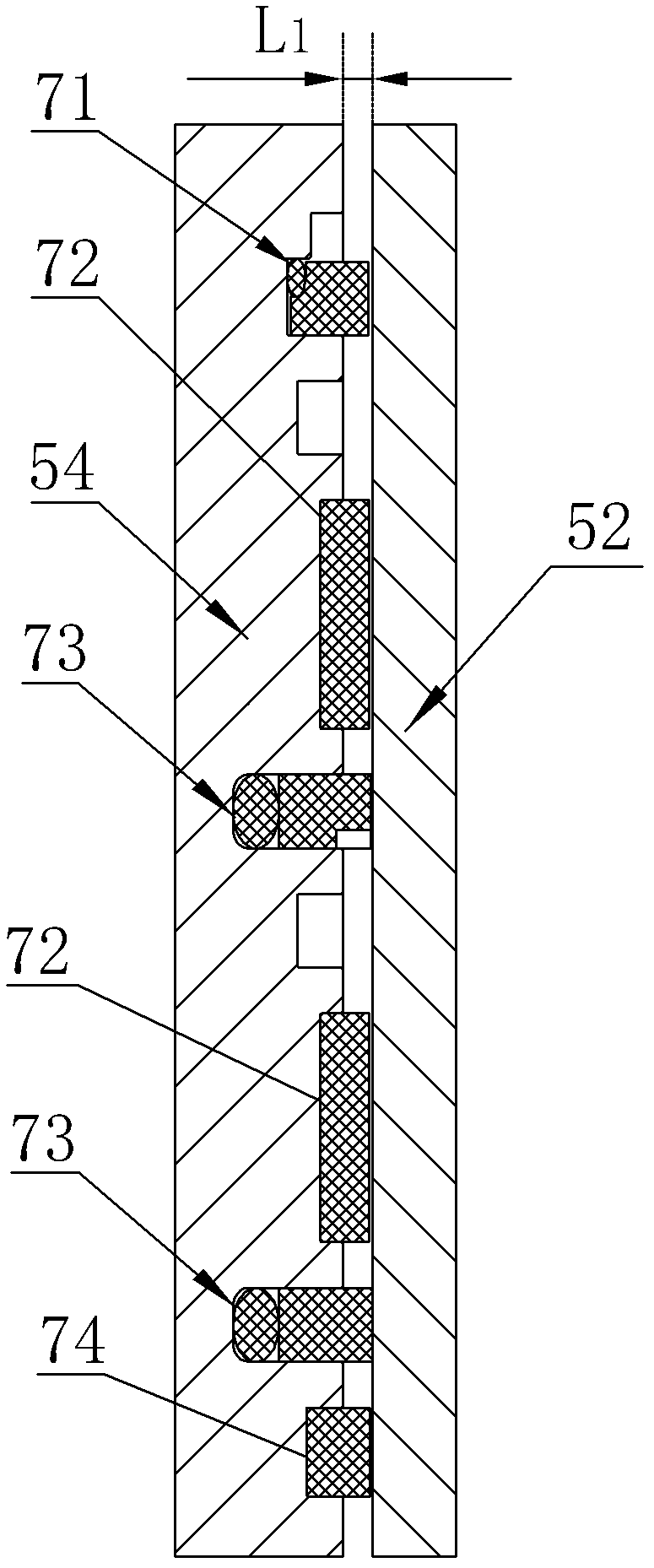
[0040] like Figure 4 As shown, a first guide ring 71 and a second guide ring 74 are respectively provided on the outer circumferential wall of the piston 54 close to the upper and lower end faces, and a first sealing ring 73 is provided in the middle of the outer circumferential wall of the piston 54; Increase the distance between the piston 54 and the cylinder 52 and ensure that the guide ring is not easy to fall off. In this embodiment, a special first guide ring 71 and a second guide ring ...


PUM


Abstract

The invention belongs to the technical field of high-pressure mould-clamping equipment, and particularly discloses a mould-clamping oil cylinder device, which comprises a piston rod and a piston, wherein the piston is connected with the piston rod, the outer circumferential wall, near the upper end surface and the lower end surface, of the piston is respectively provided with a first guide ring and a second guide ring, the middle part of the outer circumferential wall of the piston is provided with a first sealing ring, the outer circumferential wall, near the lower end surface, of the piston rod is provided with a third guide ring, the middle part of the outer circumferential wall of the piston rod is provided with a second sealing ring, and the cross sections of the first guide ring, the second guide ring and the third guide ring are respectively in a concave shape. By adopting the structure, a buffer space with a larger angle is generated when a deflection angle is formed between the piston and a cylinder barrel, so easiness in scratching of the cylinder barrel is avoided, and easiness in oil leakage is also avoided.

Description

technical field [0001] The invention belongs to the technical field of high-pressure mold clamping equipment, and in particular relates to a mold clamping oil cylinder device. Background technique [0002] The clamping cylinder device is a mechanism for providing high-pressure clamping of the vertical two-platen extrusion molding machine. like figure 1 As shown, when the mold 6 is clamped under high pressure, the moving beam 1 and the fixed beam 2 are clamped on both sides of the mold 6, one end of the tie rod 3 penetrates the fixed beam 2 and is locked together with the clamping cylinder 5, and the tie rod 3 The other end runs through the moving beam 1 and is screwed together with the clutch nut 4. Once the high-pressure oil is injected into the clamping cylinder 5, one end of the tie rod 3 can be moved to the outside of the fixed beam 2, and then the moving beam 1 is pulled closer to the fixed beam 2. , to achieve the purpose of tightly locking the mold 6. [0003] like...

Claims


Application Information

Patent Timeline
Patent Type & Authority Applications(China)
IPC IPC(8): F15B15/20
Inventor 刘贤华
Owner KEDA INDUSTRIAL GROUP CO LTD
Why Eureka
Try Eureka