
Developing method

A development method and technology of a development machine, which are applied in the development field and can solve problems such as large glass substrate size and broken glass substrate

Inactive Publication Date: 2013-07-17
BOE TECH GRP CO LTD +1
View PDF8 Cites 12 Cited by
  • Summary
  • Abstract
  • Description
  • Claims
  • Application Information

AI Technical Summary

Problems solved by technology

The size of the glass substrate in the high-generation production line is particularly large, and the rotation of the developing machine 1 can easily cause the glass substrate to break, so this developing method is not suitable for the high-generation production line

Method used


Image

  • Developing method
  • Developing method
  • Developing method

Examples


Embodiment Construction

[0025] The content of the invention of the present invention will be further described in detail below in conjunction with the accompanying drawings and embodiments.

[0026] Such as Figure 4 As shown, the developing method provided in this embodiment includes the following steps:

[0027] S1: As shown in Figure 5(a), the substrate 2 is arranged obliquely relative to the developing machine 1, the first side of the substrate 2, such as side c, is upward, and its second side, such as side d, is downward, and the side of the substrate 2 is downward. The position of the first side is opposite to the second side, that is, the c side of the substrate 2 is opposite to the d side, and the inclination angle between the substrate 2 and the developing machine 1 is θ 1 , 01 1 . Preferably, in this step, a plurality of nozzles 3 uniformly arranged in a straight line are fixed on a flat nozzle frame 4 , the nozzle frame 4 is arranged above the substrate 2 , and the nozzle frame 4 is para...


PUM


Abstract

The invention provides a developing method which comprises the following steps of: inclining a substrate relative to a developing machine table, wherein a first side edge of the substrate is upward, and a second side edge, which is opposite to the first side edge, of the substrate is downward; and an inclination angle between the substrate and the developing machine table is theta1 which is more than 0 degree and less than 90 degrees; uniformly spraying a developing solution to the substrate through a nozzle arranged above the substrate, wherein the developing time is t1; then inclining the substrate relative to the developing machine table, wherein the second side edge of the substrate is upward, and the first side edge of the substrate is downward; and an inclination angle between the substrate and the developing machine table is theta2 which is more than 0 degree and less than 90 degrees; uniformly spraying a developing solution to the substrate through the nozzle arranged above the substrate, wherein the developing time is t2. By the developing method, the uniformity of a linear width of a photoetched graph obtained by development can be improved.

Description

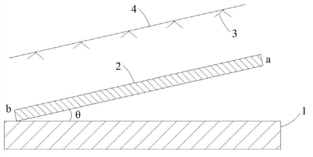
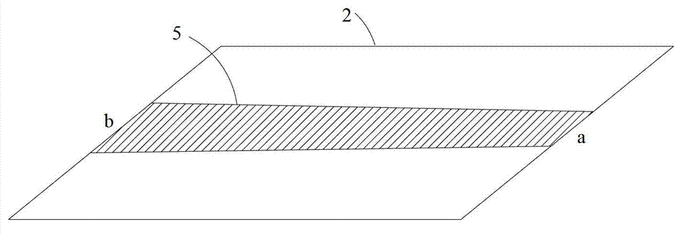
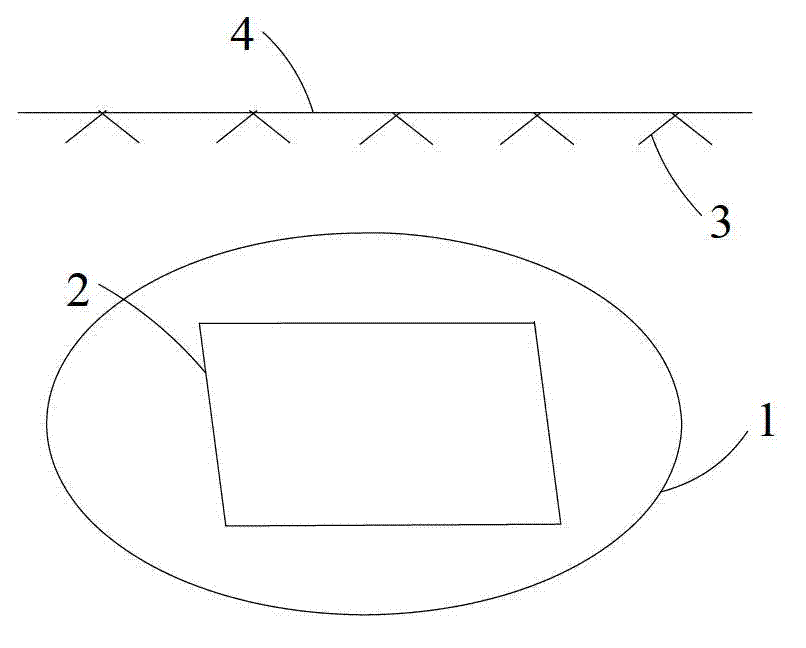
technical field [0001] The invention relates to the technical field of development, in particular to a development method, which can improve the line width uniformity of photolithography patterns. Background technique [0002] In the production process of TFT-LCD (Thin Film Field Effect Transistor Liquid Crystal Display), the photoresist coated on the glass substrate needs to be developed after exposure to obtain the required photolithography pattern. [0003] Such as figure 1 As shown, in the prior art, a development method applied to a high-generation production line, the glass substrate 2 moves along the horizontally placed developing machine 1 at an inclination angle θ, and the inclination angle θ between the glass substrate 2 and the developing machine 1 remains Invariably, a plurality of nozzles 3 arranged in a straight line are fixed on a flat nozzle frame 4 , the nozzle frame 4 is arranged above the glass substrate 2 , and the nozzle frame 4 is parallel to the glass...

Claims


Application Information

Patent Timeline
IPC IPC(8): G03F7/30
CPCG03F7/30
Inventor 黄常刚吴洪江袁剑峰
Owner BOE TECH GRP CO LTD
Learn More