
Wavelength lock and wavelength locking device with same

A technology of wavelength locking and optical splitter, which is applied in the field of optical communication, can solve the problem of less filtering functions and achieve the effect of novel structure

Inactive Publication Date: 2013-07-17
O NET COMM (SHENZHEN) LTD
View PDF2 Cites 20 Cited by
  • Summary
  • Abstract
  • Description
  • Claims
  • Application Information

AI Technical Summary

Problems solved by technology

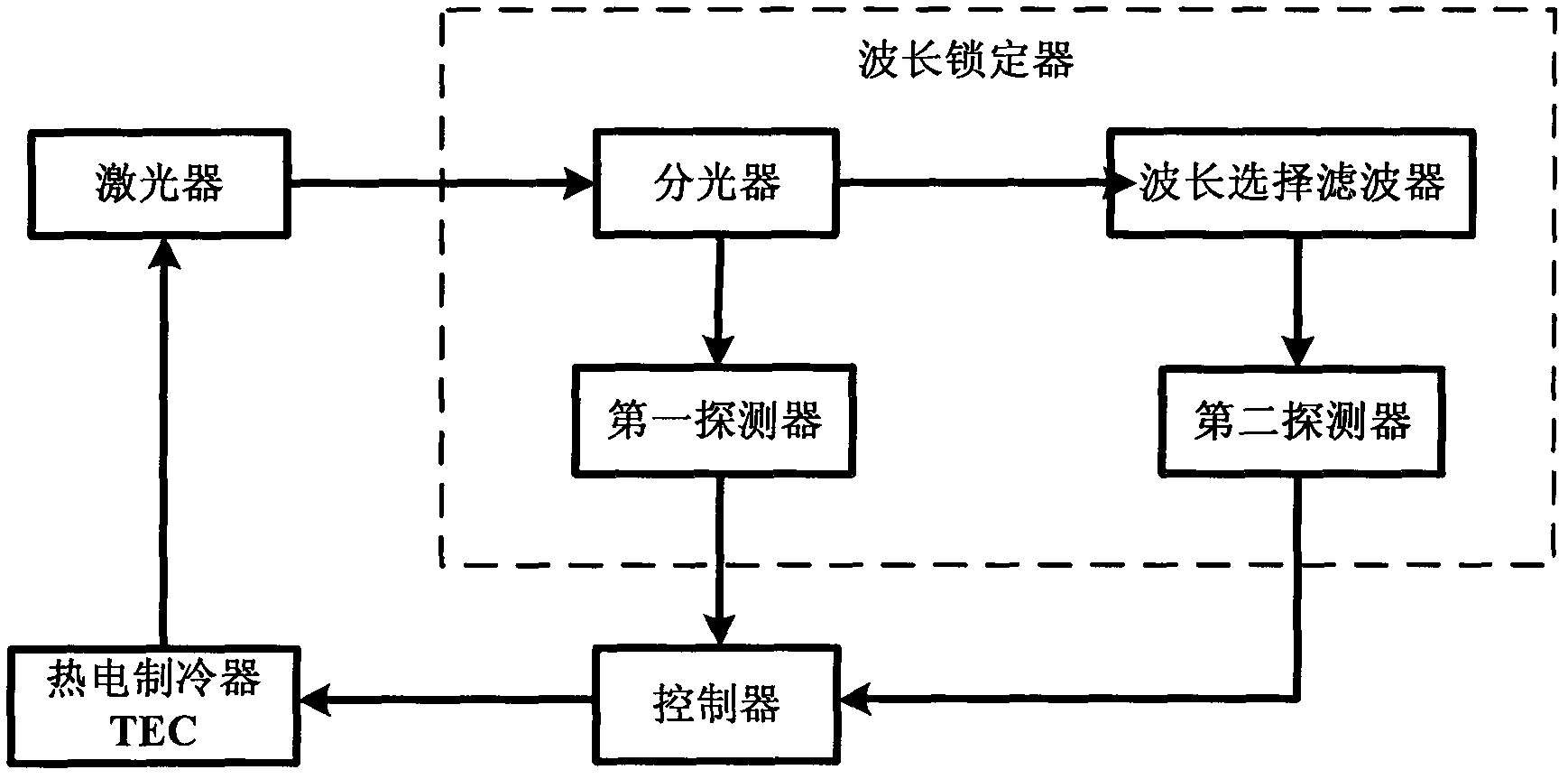
[0004] The wavelength locker provided in the prior art can also filter while realizing wavelength locking, but the filtering function is relatively less used

Method used


Image

  • Wavelength lock and wavelength locking device with same
  • Wavelength lock and wavelength locking device with same
  • Wavelength lock and wavelength locking device with same

Examples


Embodiment Construction

[0019] The present invention will be described in further detail below in conjunction with the accompanying drawings and specific embodiments.

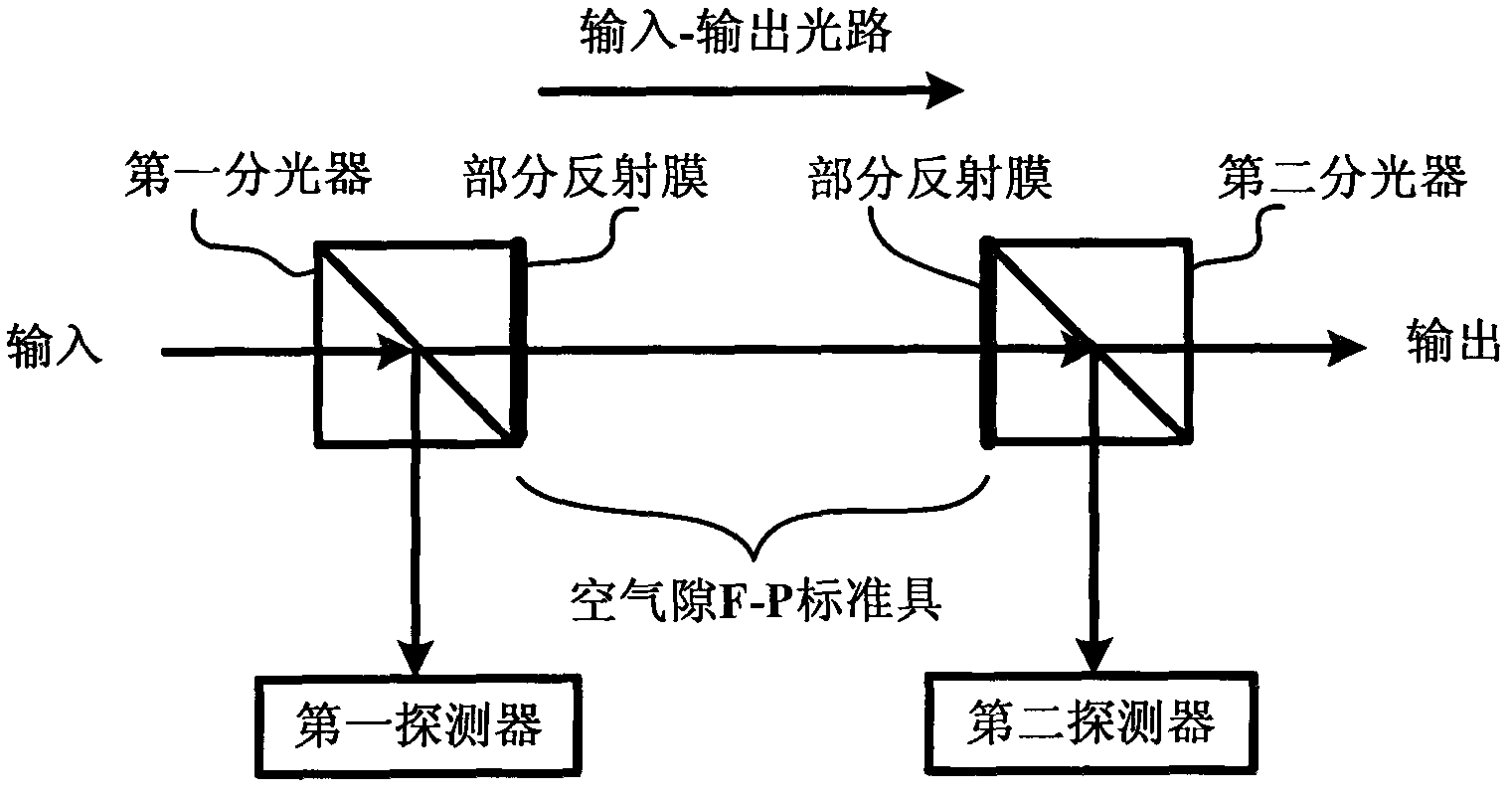
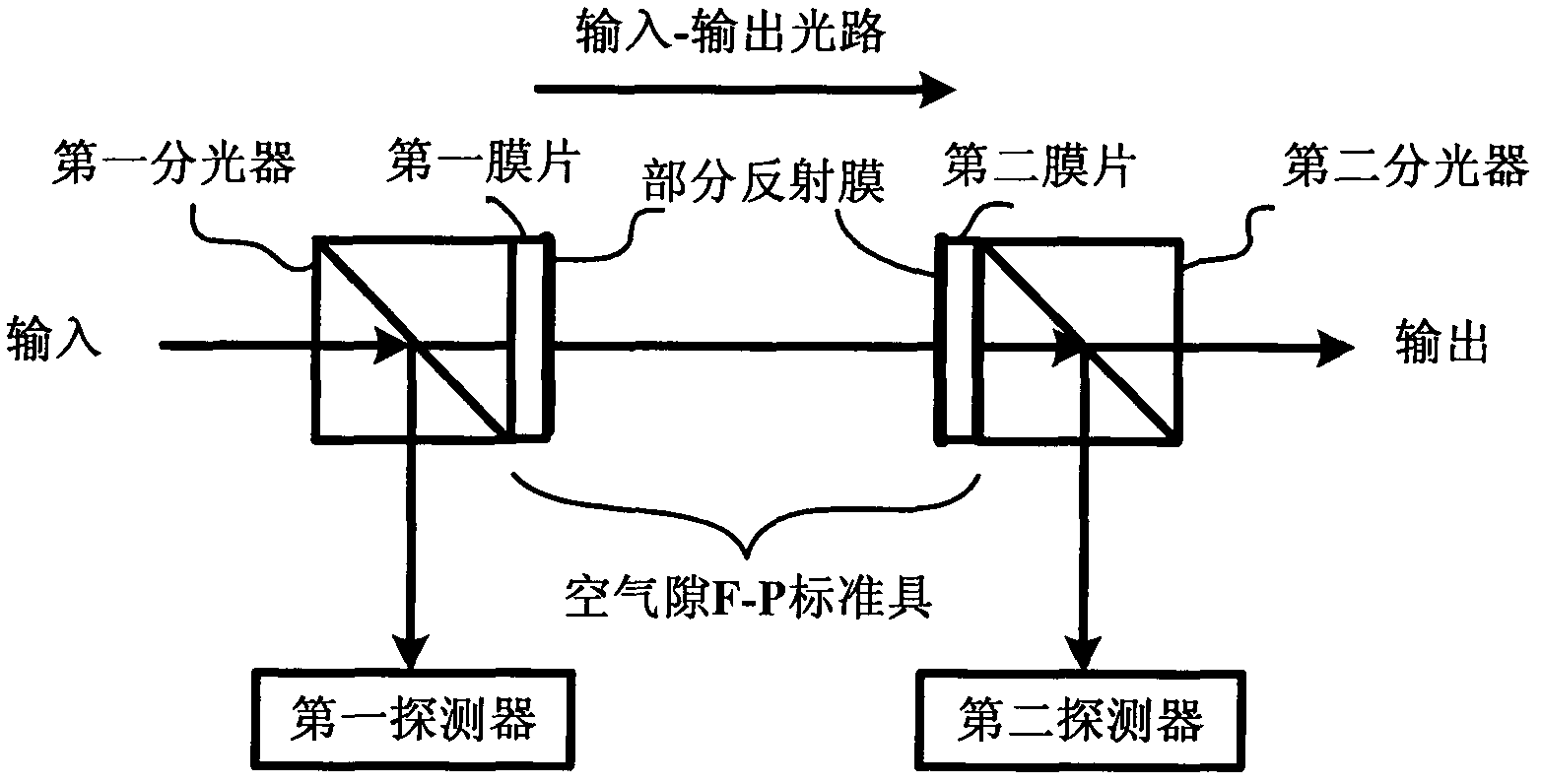
[0020] Such as figure 2 Shown is a wavelength locker provided by the present invention, which includes a first beam splitter, an air-gap F-P etalon, a second beam splitter, a first detector, a second detector, the first beam splitter, The air-gap F-P etalon is connected to the second optical splitter in sequence, and is located on the input-output optical path, and the first detector and the second detector are correspondingly connected to the first optical splitter and the second optical splitter. An output light surface of the first beam splitter, and an input light surface of the second beam splitter opposite to the output light surface of the first beam splitter are coated with a partial reflection film, and the output light surface and The input light surface is located on two parallel planes to form the air-gap F-P etalon.

...


PUM


Abstract

The invention discloses a wavelength lock and a wavelength locking device with the same. The wavelength lock comprises a first optical splitter, an F-P etalon, a second optical splitter, a first detector and a second detector, wherein the first optical splitter, the F-P etalon and the second optical splitter are located on an input-output optical path sequentially. The first optical splitter splits an input signal light beam into two beams, the first detector receives one beam and detects the luminous power of the beam, the other beam is filtered by the F-P etalon and arrives at the second optical splitter, the second optical splitter splits received signal light into two beams, the second detector receives one beam and detects the luminous power of the beam, the other beam is output along the input-output optical path, and the wavelength lock locks the wavelength according to results detected by the first detector and the second detector. The wavelength locking device comprises the wavelength lock. The wavelength lock and the wavelength locking device with the same are novel and simple in structures and capable of achieving wavelength locking and filtering.

Description

technical field [0001] The invention relates to the field of optical communication, in particular to a wavelength locker and a wavelength locking device thereof. Background technique [0002] At present, the optical channel spacing of the DWDM system is moving from 100GHz to 50GHz or even 25GHz. The system puts forward more and more strict requirements on the laser used. It is necessary to adopt effective wavelength stabilization technology to improve the wavelength stability of the laser. The wavelength locker is suitable for this demand and is the key device of the dense wavelength division multiplexing system. [0003] A typical wavelength locker optical path structure is as follows figure 1 As shown in the middle box, after the signal light from the laser is input into the wavelength locker device, it is divided into two parts by a splitter, one part directly enters the first detector as a reference signal, and the other part passes through the wavelength selection filt...

Claims


Application Information

Patent Timeline
Patent Type & Authority Applications(China)
IPC IPC(8): H01S5/0687G02B6/293
Inventor 邓云峰张彦鑫孙剑莉李连城
Owner O NET COMM (SHENZHEN) LTD
Learn More